this project is for those that don't want to use a throttle to control braking force, and prefer a brake lever (perhaps because it is what you're already used to on a bicycle for braking, and if you've ridden as long as i have, it's so hardwired it could take years to change the reflex action. in the meantime, you're left with the dangerous possibility of indecision or using the wrong control or the right one in the wrong way, in an emergency situation.)
this can be used in the simple way for any controller with an independent analog ebrake input.
this can be used in the more complex way for any controller like the phaserunner and present grinfineons that come setup with a single analog (throttle) input, which responds to voltage range below normal throttle outputs as proportional regen braking, if you use a cycle analyst v3 as well.
there is an even more complex way that i havent' developed and tested yet, to directly control the pr/gf without a ca v3; this requires voltage translation electronics to change the throttles upward-going voltage range to a downward going voltage range that is much smaller.
simple way:
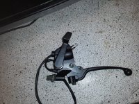
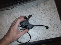
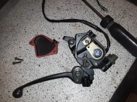
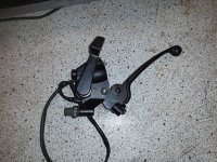
you'll need a regular cable-style brake (or ebrake) lever, but with no mechanical brake cable attached to it. if you use an ebrake lever, you can then use the switch in it to activate brake lights, either directly for low-current units, or remotely via relay for incandescent/etc. a scooter or motorcycle lever will also have a switch in it that is designed to switch the brake light on when pulled, so you can use these too. mount this to your bike wherever you prefer to use it. if you already have both a left and right brake lever that control mechanical brakes, you may either have to put this "behind" one of them, or figure out a way to split the cable from it to both the mechanical brake and the cot (see below). that's not covered here.
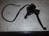
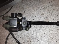
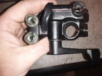
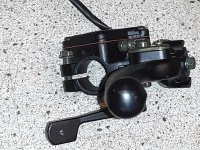
you'll need a cable-operated throttle mechanism (cot). some of these are hall output, and some are potentiometer. as long as your controller supports the full voltage range on it's independent analog brake input, it doesn't matter which one you use. the cot should come with a cable, housing, and adjusters; the adjuster end should have a cable end that will fit in your brake cable holder of the brake lever. if it doesnt', you'll have to change the cable to a regular brake cable, and come up with a way to fasten it to the cot's pulley, if it doesnt' already have the correct knob at that end.


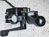
mount the cot unit wherever you prefer; if it's not weatherproof it should go inside whatever *is* weatherproof on your bike or vehicle.


the cable most come wiht is pretty short, so you might have to replace that cable and housing with one that is long enough to reach the spot you want it to go. you may also have to change the adjusters to fit your brake lever, unless you just use a regular brake cable and housing, and use the adjusters already on the lever. the adjusters on it are not meant for brake levers, but for cable-throttlegrips, so it's unlikely the threading and size will "just fit" your brake lever.

.jpg")
the electrical cable is also pretty short, and probably has a tamiya or similar plug on it; this probably wont' fit whatever controller you're using, so you'll have to fix that, too, while you're splicing on a longer cable. so far the ones i've seen use red for 5v, black for ground, and green for the signal output. wire these up to the appropriate pins on your controller's analog brake input.
every controller's setup program and method is different, so none are covered here. but you'll need to set up that input for the voltage range you actually get out of the cot, for the range of travel you get out of the lever for the braking movement you prefer. it's possible that the cot wont' pull it's full range for the amount of lever travle you can get. in my case, i got exactly the full cot range for the full lever range; i doubt that will happen for every cot and lever combo.
once it's setup, all you have to do to engage braking is to use the lever naturally.
there may be controllers that require you to engage a brake switch at the same time or before sending the control voltage to the analog brake input. if so, you can use an ebrake lever and use that switch to do this.
this can be used in the simple way for any controller with an independent analog ebrake input.
this can be used in the more complex way for any controller like the phaserunner and present grinfineons that come setup with a single analog (throttle) input, which responds to voltage range below normal throttle outputs as proportional regen braking, if you use a cycle analyst v3 as well.
there is an even more complex way that i havent' developed and tested yet, to directly control the pr/gf without a ca v3; this requires voltage translation electronics to change the throttles upward-going voltage range to a downward going voltage range that is much smaller.
simple way:
you'll need a regular cable-style brake (or ebrake) lever, but with no mechanical brake cable attached to it. if you use an ebrake lever, you can then use the switch in it to activate brake lights, either directly for low-current units, or remotely via relay for incandescent/etc. a scooter or motorcycle lever will also have a switch in it that is designed to switch the brake light on when pulled, so you can use these too. mount this to your bike wherever you prefer to use it. if you already have both a left and right brake lever that control mechanical brakes, you may either have to put this "behind" one of them, or figure out a way to split the cable from it to both the mechanical brake and the cot (see below). that's not covered here.
you'll need a cable-operated throttle mechanism (cot). some of these are hall output, and some are potentiometer. as long as your controller supports the full voltage range on it's independent analog brake input, it doesn't matter which one you use. the cot should come with a cable, housing, and adjusters; the adjuster end should have a cable end that will fit in your brake cable holder of the brake lever. if it doesnt', you'll have to change the cable to a regular brake cable, and come up with a way to fasten it to the cot's pulley, if it doesnt' already have the correct knob at that end.
mount the cot unit wherever you prefer; if it's not weatherproof it should go inside whatever *is* weatherproof on your bike or vehicle.
the cable most come wiht is pretty short, so you might have to replace that cable and housing with one that is long enough to reach the spot you want it to go. you may also have to change the adjusters to fit your brake lever, unless you just use a regular brake cable and housing, and use the adjusters already on the lever. the adjusters on it are not meant for brake levers, but for cable-throttlegrips, so it's unlikely the threading and size will "just fit" your brake lever.
the electrical cable is also pretty short, and probably has a tamiya or similar plug on it; this probably wont' fit whatever controller you're using, so you'll have to fix that, too, while you're splicing on a longer cable. so far the ones i've seen use red for 5v, black for ground, and green for the signal output. wire these up to the appropriate pins on your controller's analog brake input.
every controller's setup program and method is different, so none are covered here. but you'll need to set up that input for the voltage range you actually get out of the cot, for the range of travel you get out of the lever for the braking movement you prefer. it's possible that the cot wont' pull it's full range for the amount of lever travle you can get. in my case, i got exactly the full cot range for the full lever range; i doubt that will happen for every cot and lever combo.
once it's setup, all you have to do to engage braking is to use the lever naturally.
there may be controllers that require you to engage a brake switch at the same time or before sending the control voltage to the analog brake input. if so, you can use an ebrake lever and use that switch to do this.


.jpg")


")