PowerVeloCity F18-100 controller, not working

Santacruz

100 W
Joined
Jun 18, 2015
Messages
148
Hi all,
I have for sometime been building my new bike.
I will try to keep this simple and straight forward.
I finally got to the point of switching on to test and set up, but nothing.
I have one of those Chinese hall testers.
Using that, Motor phases are ok.
Motor halls are okay.
Plugged into controller, I am not getting any throttle reading.
I am using a CA3 (direct plug into controller) also and this shows the throttle climb when I use it and the PAS works and the ebrake shows it's working. (Throttle is a slim line hall from grin, so is correct for the CA3, as is PAS, also from grin and direct plug and play with CA3). The speedometer also works when I spin the back wheel.
But nothing at the motor. I also checked the hall power and when the controller is switched on it shows about 4.35v between red and black wires of the hall plug.
The app will not connect at all on my android phone (controller has built in BT, that was floating loose when I first got the controller, I pluged this back in) and I have done all the cache clearing and unpaired all BT devices. It shows the PowerVeloCity-i when bike turned on, but will not connect.
My iPhone connects and shows connected, but selecting program, shows failed due to response timed out, that is to read or write.
The dash shows no information at all, everything is 0.
The CA3 shows battery voltage (90v).
I am at a loss what to check. I have been over all the wiring and it is correct and connected. The CA3 registers everything and it is getting it's power from the controller (6 pin controller to CA3).
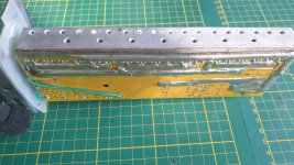
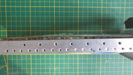
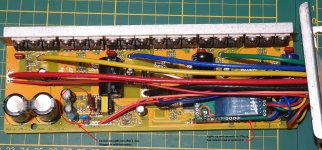
I pulled the controller out and checked the board and as far as I can see it looks good. But I did notice that the board is curved badly on the mosfet side. If you look at the photos you will see what I mean. Should I re-solder it to get it flat, as I have different mosfet leg lengths.
Any help would really be appretiated. I have contacted PowerVeloCity, but not had any answer.
20200410_213437.jpg
20200408_170239.jpg
20200408_170223.jpg
 
Santacruz said:
Hi all,
I have for sometime been building my new bike.
I will try to keep this simple and straight forward.
I finally got to the point of switching on to test and set up, but nothing.
I have one of those Chinese hall testers.
Using that, Motor phases are ok.
Motor halls are okay.
Plugged into controller, I am not getting any throttle reading.

0

0

0

Your pics do not show, friend. Please fix and we will try to help....
 
@DogDipstick I have changed the photos to Google drive, hopefully that will work, although for me they were okay.

@999zip999 Yes, I guess he will, I have had no problems in the past, but sadly on his forum is a crap load of spam constantly posted and I fear my post will just get lost in it all. I did also send him a message via his website, but with this present world wide situation, I do not know what is happening. So, that is the reason for posting on here.
 
Log into app and go to settings and hit the connect button.I have to do that every time to get it to work but after that it is great.
 
I have tried every permutation possible with my Android phone (Galaxy S9+ which works fine with every other bluetooth device I have). I have removed all bluetooth devices, cleared bluetooth cache, un-installed and reinstalled the PowerVeloCity app.
But, my Android will not connect at all. I use the app to connect, not the bluetooth. I have follwed exactly the instructions from PowerVeloCity.
But, I can connect from settings with my Iphone. However, when I try to read any settings I get failed due to time out. I have tried making settings to update and I get failed to write due to time out response. I have tried many many times and have had no luck.
 
Santacruz said:
controller has built in BT, that was floating loose when I first got the controller, I pluged this back in
was the controller ever connected to the battery while this was loose?

if so, it could easily have been damaged by touching something inside that it shoudln't have.

or just banging around in there could have damaged a component, depending on what is exposed, etc. (this is less likely)

either would require replacing the module, but both would explain bt access being problematic, especially if it is the radio or antenna that is damaged.
 
No, the bluetooth module I found loose when I received it.
I herd something rattle when I unpacked it, so took it apart and found the module floating loose.
I just plugged it back in and nothing else looked out of place or damaged.
The radio antenna was (is) soldered to the bottom of the circuit board, so not part of the plug in module.
You can see in one of the photo's I posted, that condition wise it looks good.
The one thing that concerns me is the bent circuit board were the mosfets are soldered on. The legs are close to the board at the ends, but a good 1/8" longer in the middle. I don't know if this will affect performance or loads on the different mosfets.
So when I fitted it to the bike, everything was as it should be.
The photo's I posted is after I have taken it back off the bike to have a look and see if I could see anything wrong.
I have done a test when on the bike with the Chinese tester as In my first post.
Now I don't know what to test or check.
 
I should also add, I have circuit tested from the CA3 circuit board to the ends of every connection, to make sure I have no broken wires or bad connections.
They all check out fine and I have also double checked that they are all wired correctly and they are.
The last thing I can think of, is to check all the plug wires to the circuit board of the controller.
 
Today I checked all the plug wires to the PCB and they are all good and have continuity.
I powered the controller up with test wires (power, ground and switch).
The Bluetooth lit up and my iPhone automatically connected. But I cannot read or write to it, I just get response timed out.
My android Samsung S9+ cannot find it at all.
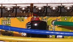
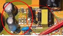
Also as per the photo, I noticed that one part of the board gets very hot very quickly. I don't know what this part of the board is in charge of, or if that's normal, but I ended any further testing.
https://drive.google.com/open?id=1Y1sNWpiWthJYN6RV6vcQ8xT18rA7xJ51

I am not very impressed with this controller. The quality is not that good, the mosfets soldering is quite bad to me, see previous post photos.
I also noticed that the PCB is not wide enough to fit the case slots, so when assembled the whole lot is hanging by the mosfets.
My next thing to do, is get another better quality more reliable controller from somewhere else.
 
I'm only a hobbyist electronics chap so others could help a lot more and I know this is from a year ago but as you pointed me to the thread I thought I'd note:

Top right there appears to be a blown capacitor
cap.JPG

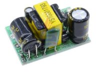
The location you circle appears to be a DC/DC converter - similar - note the small coil similar to this one on a buck converter:
Buck.JPGLV DCDC.JPG

If the cap is blown and short circuited it may be pulling a power rail down and preventing the micro from running

This is probably running a 5V rail and or 3.3V for the micro, bluetooth etc, which will tend to get hot if either it is faulty or something downstream is damaged and drawing too much power.

First thing is replace the blown cap and have a spare in case it blows again and wear glasses

I'd try disconnecting the BT module and probing the micro that is under it (carefully to not short out pins) and see if it's now running.

You could see whether the BT behaves the same way if it's powered up on it's own - if there's no difference it may indicate there's no comms between it and the micro.

If there is power to the micro but it is doing nothing it's probably dead

If the hot spot dissapears then the BT might be faulty and drawing too much power.

I'm guessing you've already disconnected everything else, checked none of the wires are shorted together, that there is continuity to all of them etc?


Freeze spray is a good way to find other hot spots (if another part is drawing the power to cause the low volt power supply to overheat then there's a good change it will also get hot.

IR camera's are great if you have one or a friend has one. FLIR make one for around £100 and I've used it in the past to find electrical faults (and gaps in insulation and damp spots and underfloor heating pipes etc around the house).
 
Thanks for the info.
I never noticed that cap. I will have to have a closer look.
The controller is boxed up and packed away.
In the end I replaced it with a Sabvoton 96120, which after 1000kms is working very well.

As for the PV controller, I did a thorough check of all the wiring and it all checked okay. But I never noticed that blown cap.
But I am still very unimpressed with the build quality. The way the mosfets are mounted and the fact that the circuit board does not fit the casing very well. Things that can be fixed, but then again, I bought what I considered to be a modified working controller and not something I would have to rebuild.
 
Could be a bit of dirt but hope that fixes it but if the micro is blown it's probably more tricky.
And yes, I agree, not impressive quality

I've been looking for higher voltage so have limited options, there's nothing much at 150V and not many at 120v
The YKZ120150 is a little cheaper and goes up to 120v allegedly https://www.aliexpress.com/item/1005002095335029.html
 
Back
Top