
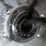
I've been trying to repair my grandson's Rad Power Mini, after his two years of commuting to work in Minneapolis with minimal maintenance. Turns out the big killer has been the failure of the Bafang hub motor bearing on the freewheel side. Now, I’m trying to figure out how to remove and replace that bearing. I’m making a slotted freewheel puller, but it looks like I’ll have to cut the motor wiring to remove that housing to replace the bearing. The bearing ID is too small to clear the nut, washers, and connector. That seems almost like some dumb GM idea. Has anyone actually done this repair and, if so, how'd you do it?
You are using an out of date browser. It may not display this or other websites correctly.
You should upgrade or use an alternative browser.
You should upgrade or use an alternative browser.
Rad Power hub motor bearing replacement
- Thread starter TWDay72
- Start date
Usually the washers and nuts come off the cable first, then the cable passes thru easily. You don't show those or the connector itself, but these typically use Higo or Julet connectors, which easily pass thru the washers/nuts.
That's interesting...and odd. Is the conenctor "overmolded", just one solid piece, or is it something that comes apart, like unscrewing the "boot", to access the back of the contacts. If you can, then if they are soldered on then that means they pass the wire thru the nuts/washers/bearing and then put the connector on. If it's overmolded, it means they put the cable thru evertying with connec tor already on it, and then solder it inside the motor to phases and halls.
Either way, the "easiest" way to get it off is the same way they did it.
If you do have to cut and splice the cable, the best place is inside the motor, so you dont' have to waterproof the connections externally.
Either way, the "easiest" way to get it off is the same way they did it.
If you do have to cut and splice the cable, the best place is inside the motor, so you dont' have to waterproof the connections externally.
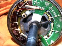
Unless I'm missing something, the manufacturer did not intend this to be a repairable part. The circuit board, pictured, is a ways from a user-friendly serviceable part. The wire exists the motor shaft at 90 degrees on the right side of this picture. Not impossible, but the existence of 3 identically sized white wires (of a total of 9 wires) makes reassembly awkward at best. That also makes cutting the cable and reassembly a dubious tactic. The 9-pin connector (6 pins around the inner edge of the connector), also pictured, is a molded piece that almost had to have come preassembled with the cable. I can't think of a way a manufacturer could have assembled that connector after wiring the motor. You can see the six small wire connections on the PCB. The large power wires (blue, green, yellow) appear to be soldered directing to the motor coils.
Attachments
None of these things are "intended" to be repaired; they build them all as throwaway items, like most stuff these days.TWDay72 said:Unless I'm missing something, the manufacturer did not intend this to be a repairable part.

But it doesn't mean you can't repair ti...just that it's a PITA.
At least this one has a PCB--many do not, and one must take extreme care not to break off hall sensor legs and such. So you have it easier on this one.The circuit board, pictured, is a ways from a user-friendly serviceable part.
I only see one white wire. Where are the other ones, and what do they go to?The wire exists the motor shaft at 90 degrees on the right side of this picture. Not impossible, but the existence of 3 identically sized white wires (of a total of 9 wires) makes reassembly awkward at best.
What I see is six thin wires, the Red (5v), Black (ground), white (speed sensor), and the Yellow, Blue, and Green hall sensor wires.
Then there are three thick wires, the Yellow, Blue, and Green phase wires.
So...while it will be a PITA to unsolder the phase wires, the other six on the PCB are easy as long as you keep track of which color is on which pad now, and put them back the same way.
What I would usggest on the phase wires is to cut them somewhere else other than at the present splice points, say, right at the end of the present jacket that comes out of the motor axle (just past the 90 degree point)...but *only* cut those there, not any of the thin wires, which would be left at their original length to be resoldered as they are to their original posistions on the PCB.
This "overmolding" is the normal way waterproof connectors are installed, done at the cable factory. I was just hoping that yours was not one of those, as it would've made it easier for you.The 9-pin connector (6 pins around the inner edge of the connector), also pictured, is a molded piece that almost had to have come preassembled with the cable. I can't think of a way a manufacturer could have assembled that connector after wiring the motor.
YOu can, of course, just cut and splice everything outside the motor, it just won't look as neat when done, and is a bit more difficult to waterproof.
As long as you have enough cable, then on the outside cut-splice, I would reocmmend staggering the splices so that none of them overlap each other. this makes the resulting cable splice area "thinner" in crosssection, and it also makes it much less worrisome to reinsulate the splice points from each other so they can never short.
motomech
10 MW
When you get the cover free of the cable, just drill two sm. holes in the cover that line up w/ the outer brg. race and knock it out w/ a sm. punch. The holes can be plugged w/ JB Weld. The brg. should have some numbers on the race that can be matched at a brg., belt and chain supply store. Carefully pry off the seal (if there is any), clean out what little grease that is in there and repack. Install w/ a socket and hammer. You can put the brg. in the freezer for a while before installing.
I've had to cut and splice the power cable before and it's not the end of the World. Just use lot's of quality shrink-fit. A piece on every wire and a big piece over the whole splice.
I've had to cut and splice the power cable before and it's not the end of the World. Just use lot's of quality shrink-fit. A piece on every wire and a big piece over the whole splice.
Excellent advice. I have nothing to lose but time, so why not? I've looked at other Bafang hub motors and some appear to use a considerably smaller connector. I wonder if they all have the same connector problem or if some are actually made with a connector that clears the nuts and bearing?
I've pulled a bunch of motorcycle wheel bearings in my life. The easiest tactic I've found for removing a steel race bearing from an aluminum hub is with a heat gun. Cook the surrounding aluminum to just a bit above where it is uncomfortable to touch and the bearing practically falls out. The reverse tactic works for installation, too. Heat the aluminum hub again and the bearing slides in easily. If you do replace the bearing that way, cool the hub fairly quickly to keep from cooking the grease in the new bearing. Probably not a new tactic for you guys, but there you go. 8)
I've pulled a bunch of motorcycle wheel bearings in my life. The easiest tactic I've found for removing a steel race bearing from an aluminum hub is with a heat gun. Cook the surrounding aluminum to just a bit above where it is uncomfortable to touch and the bearing practically falls out. The reverse tactic works for installation, too. Heat the aluminum hub again and the bearing slides in easily. If you do replace the bearing that way, cool the hub fairly quickly to keep from cooking the grease in the new bearing. Probably not a new tactic for you guys, but there you go. 8)
"I only see one white wire. Where are the other ones, and what do they go to?" The six solder connections just above and to the right of where the cable exits the axle are all for the sensor wires (assuming that's what they are) to the motor connector. Could be there is a stripe on those white wires, but I can't see one without disassembling the whole thing.
motomech
10 MW
The sm. connector is called a 9-Pin connector and comes on most every low to mid power capable motor. They are good up to about 40 Amps or so w/ a 48 Volt system. In your case the Rad motor is not so rad.I've looked at other Bafang hub motors and some appear to use a considerably smaller connector. I wonder if they all have the same connector problem or if some are actually made with a connector that clears the nuts and bearing?
But they are hard to find in the States and many of us always throw one in every order coming from Asia. I once got one from Luna, but I think they stopped carrying them. You might ck Ebay.
The white wire is for a speed sensor, probably not used in that system.
The other 8 wires are;
5 thin;
Blk - Hall neg.
Red - Hall pos.
Yellow - Hall signal
Blue - Hall signal
Grn. - Hall signal
3 thick;
yellow - phase
Blu - phase
Grn. - phase
AFAICS, all of those wires to those solder pads, visible under the PCB in your picture, are all clearly colored wires, except for the one white wire (which should go to the SP pad). The five colored wires are the Red (5v), Black (ground), and the Yellow, Blue, and Green hall sensor wires.TWDay72 said:"I only see one white wire. Where are the other ones, and what do they go to?" The six solder connections just above and to the right of where the cable exits the axle are all for the sensor wires (assuming that's what they are) to the motor connector. Could be there is a stripe on those white wires, but I can't see one without disassembling the whole thing.

The only other white things I see that even remotely resemble wires (to me) are the five tie-down strings securing the PCB to the windings.
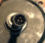
BTW, that connector is apparently called a Julet Z916:
https://www.ebikes.ca/learn/connectors.html#julet-z916
This octagonal style motor plug from Julet has higher gauge wire and larger pins than the Z910 connector, but less current capability than the L1019. It is quite popular for generic mediium power ebikes and kits on the market, including many motors in the Rad Power bike lineup. The connector has 3 phase wires in the middle and 6 signal lines around the perimeter, allowing for an additional motor speed sensor but not a separate speed sensor and temperature sensor like the L1019 plug.
We don't plan to use this connector in any of our own motors as we find the L1019 to be superior, but given its popularity in existing ebike systems we are looking to make an adapter cable so that people can still have plug and play upgrade options from us.
https://en.junleidq.com/product/5.html
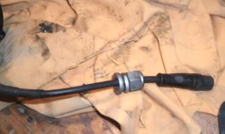
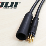
That "9-Pin connector and comes on most every low to mid power capable motor" is good for up to 40A? That would be almost 2,000 watts. I guess I'm confused about what power classifications mean with eBikes: low vs mid vs moderate vs high power. I don't see me ever needing more than a 750W motor on an eBike, so maybe I should look at a replacement controller and motor with this connector set? I've attached a picture of the kind of connector I am talking about and wondering if it is small enough fit through the nut, washers, and bearing.
When it comes to a picture that I took, never put too much weight into hoping I got it all. Cameras and me are not on friendly terms. There are two small white wires under that bundle that didn't show up in my pictures. They might be striped, but I couldn't see that from the current wiring bundle status. We'll know better when i take it apart.
When it comes to a picture that I took, never put too much weight into hoping I got it all. Cameras and me are not on friendly terms. There are two small white wires under that bundle that didn't show up in my pictures. They might be striped, but I couldn't see that from the current wiring bundle status. We'll know better when i take it apart.
Attachments
40A on the phase wires is different than 40A at the battery, so you can't measure the power that way. You can have a 9 or 10A battery current and still get 40A phase currents under enough load, but ti's the battery current that is used to calculate the power usage, because the phases are at a different voltage (lower) when under that load, and the current and voltage are not in phase with each other.TWDay72 said:That "9-Pin connector and comes on most every low to mid power capable motor" is good for up to 40A? That would be almost 2,000 watts.
It depends on the peak currents in the phase wires for which connector and wiring gauge is appropriate. If that bike has high phase currents, it could warm up the smaller Higo wiring and contacts, whenever it's under loads like hill climbing or startup from a stop, etc. The slower the speed and the higher the load, the worse the problem is.guess I'm confused about what power classifications mean with eBikes: low vs mid vs moderate vs high power. I don't see me ever needing more than a 750W motor on an eBike, so maybe I should look at a replacement controller and motor with this connector set?
You can always save the old connector/cable pair and try it out with the smaller one, and if you ever run into problems, swap them back.
That looks like the regular old style Higo connector:I've attached a picture of the kind of connector I am talking about and wondering if it is small enough fit through the nut, washers, and bearing.
https://www.ebikes.ca/learn/connectors.html#higo-z910
which they don't sell as separate male and female ends, but they have an extension cable you can cut in half to make a new motor cable, use the other for the controller end.
https://www.ebikes.ca/shop/electric-bicycle-parts/wiring/z910-ext-60.html
I think I've seen them on Amazon and ebay and other places, too.
Ah. Well, at least two white wires is much easier to deal with than six, which is what you'd said before.When it comes to a picture that I took, never put too much weight into hoping I got it all. Cameras and me are not on friendly terms. There are two small white wires under that bundle that didn't show up in my pictures. They might be striped, but I couldn't see that from the current wiring bundle status. We'll know better when i take it apart.
Either way, as long as you mark both ends of each of the wires as you cut them, and only cut one at a time, for any that are the same color, you can easily keep track of what needs to splice back together, evne if they really are all the same color.
I see the confusion, but what I wrote was "the existence of 3 identically sized white wires (of a total of 9 wires) makes reassembly awkward at best." So, as you or someone noted, 3 large gauge wires and 6 small gauge wires with 3 of those apparently being white (at least as seen from outside of the harness).
I'm going to have to put down my beer and study the "phase current" concept. I'm not a power electricity guy (mostly an audio guy) and everything I've read so far puts phase current limits around 1.5x battery current at max (which is risking controller outputs [something I do understand] and motor heating). So expecting a 40A phase current from a 12-15A capable battery supply seems to contradict that. As i said, my understanding of motor operation is shaky in this technology.
In fact, I was looking at ordering 3-4 of those Higo extension connectors from eBay for this experiment. It's hard for me to imagine going through all of this to replace a bearing and leaving everything in place to force the same overly complicated repair the next time.
I meant to add this to an earlier post. If it seems like I'm stalling on this repair, I probably am. I'm 72 and my eyesight sucks at best but the reason I'm on an eBike instead of a motorcycle as I have been for more than 55 years is two years ago I was diagnosed with occular myasthenia gravis and that results in double-vision. That has reduced my abilities in small circuit repairs dramatically.
TWDay72 said:I'm not a power electricity guy (mostly an audio guy) and everything I've read so far puts phase current limits around 1.5x battery current at max (which is risking controller outputs [something I do understand] and motor heating). So expecting a 40A phase current from a 12-15A capable battery supply seems to contradict that.
It's possible that's correct; I don't recall the exact ratios as a max. Just was recalling stuff from testing a controller a while back that did actually log currents and stuff, and thought I remembered a much higher ratio with it at some point. Mostly was just pionting out that the current on a phase couldn't be used with the battery voltage to determine power.
I'm only 52, but have pretty poor eyesight when working on small close stuff (a shame since once I could see like a microscope!), so I use a camera and computer monitor to magnify eveyrthing for me:TWDay72 said:I'm 72 and my eyesight sucks at best but the reason I'm on an eBike instead of a motorcycle as I have been for more than 55 years is two years ago I was diagnosed with occular myasthenia gravis and that results in double-vision. That has reduced my abilities in small circuit repairs dramatically.
https://endless-sphere.com/forums/viewtopic.php?f=30&t=105711&p=1551378&hilit=camera+workstation#p1551378
If you have a celphone that supports one of the external display mirroring functions, you can get holders for them to use them the same way. Or the still camera you used to take pics, some have a port to display live on an external monitor. Or you can just buy something like the "student cam" I've got in those pics.
Oh man, now I need to spend more money! Back in my medical devices days, the company had a camera that could blow up the view to the point where I could identify a fused transistor in an LSI SMT chip. Your rig looks like something I should be implementing. My hands are still solid, but my eyes are garbage. My eyes have never been great, especially the left one, but double-vision and a soldering iron is a lousy combination. :lol:
Yeah, this camera/monitor makes it possible for me to work on stuff smaller than my head, with wires smaller than my fingers.TWDay72 said:Oh man, now I need to spend more money! Back in my medical devices days, the company had a camera that could blow up the view to the point where I could identify a fused transistor in an LSI SMT chip. Your rig looks like something I should be implementing. My hands are still solid, but my eyes are garbage. My eyes have never been great, especially the left one, but double-vision and a soldering iron is a lousy combination. :lol:
It won't help me see stuff much smaller than the stuff in the pics, but as long as I don't solder the camera itself in the process, it works ok. My hands dont' work that well either anymore all the time, but if i do the work during the times that they *do* work ok, and stop when I begin to have problems, I don't screw up too much stuff.
I have to use a 42" computer monitor for reading / posting on the internet, or else enlarge the laptop screen so much that it won't fit more than a portion of a screenful of stuff, and I have to then scroll around a lot both horizontally and vertically just to write a reply or read a post.
BTW, I got both the camera and the monitor at goodwill, but you can probably find stuff like them used on ebay for relatively cheap. The exact one I have (AFAICT), is the Videolabs Student Cam here:
https://www.ebay.com/p/1300172131
which is about $50, and it comes iwth the cables (mine didnt'). To use it without the cables, if you find one cheaper and don't mind the DIY/hacking, you can find the pads for Svideo (Y and C, I think?) on the board, and the 12v / ground for power, and wire them out to external connectors, and plug them into your most convenient display with Svideo input.
If you need higher resolution than "TV" (basically 640x480), you' can get a "USB microscope" and display it thru your ocmputer's monitor. They're not expensive either, though they go up the higher resolution you need, and the more adjustability you need out of it's setup.
https://www.ebay.com/sch/i.html?_from=R40&_trksid=p2047675.m570.l1313.TR12.TRC2.A0.H0.TRS0&_nkw=%22USB+microscope%22+&_sacat=0
https://www.amazon.com/s?k=usb+microscope&ref=nb_sb_noss_2
It has been a bit since I came back to this project. I did pull the clip to remove the wiring, cut the wires near the board and motor coils, and try to remove the bearing. As best I can tell, the bearing must have heated and/or spun in the casing because any number of the usual tactics I've used to remove bearings from a hundred or so motorcycle wheels, motors, etc just resulted in distorting the casing. I have a 2nd failed backup motor, so that isn't a show stopper. However, removing the circuit board to get to the wiring requires desoldering 3 Hall Effect transistors and they are practically pressure-fitted into the PCB. I am not at all confident that I can get the cable replaced and the PDB remounted without doing some weird damage that I won't discover until the whole mess is reassembled. I opted to replace the motor with a $260 "real 750W Bafang." No, I don't buy the "real" argument, but it was the cheapest replacement I could find.
I learned a lot in the process, though. For one, I would never buy a bike that uses the WP8 12mm connector, when the 10mm Z910 connector carries as much current and will fit through the nut, washers, and bearing without cable removal. It just makes sense to make something as expensive as an electric motor repairable.
I learned a lot in the process, though. For one, I would never buy a bike that uses the WP8 12mm connector, when the 10mm Z910 connector carries as much current and will fit through the nut, washers, and bearing without cable removal. It just makes sense to make something as expensive as an electric motor repairable.
Similar threads
- Replies
- 4
- Views
- 407
- Replies
- 4
- Views
- 679
- Replies
- 1
- Views
- 732