
You are using an out of date browser. It may not display this or other websites correctly.
You should upgrade or use an alternative browser.
You should upgrade or use an alternative browser.
Re wiring diagram for a 5 to 1 wiring harness
- Thread starter modaniel
- Start date
e-beach
10 MW
So are you talking only Hall Sensor wires or phase and battery wires as well?


e-beach said:So are you talking only Hall Sensor wires or phase and battery wires as well?
Sorry for the slow reply!!! I have been having a crazy month.
Actually, I am referring to the headset on the front of the bike. So that is the brake levers, throttle, display etc.
bangbang said:Is the cable your working on have 9 pins or 8 etc ?
It's 9 pins.
TommyCat
10 kW
So not for a Bafang mid drive or a Magic Pie V5 DD...
Exactly what system are you working on??? Detailed controller information perhaps.
Exactly what system are you working on??? Detailed controller information perhaps.
e-beach
10 MW
If you can post a picture it would help. Make sure the picture is in good focus.
docw009
1 MW
He's talking about the harness that fans out to the display (5 wires), throttle (3 wires) and two brakes (2 wires). Since all three use a common ground, that's 8 wires. I'm not familiar with the 5:1 harness. Is the fifth item lights?
Take the connector off the old controller, if it's dead, and wire that to the new one. You can get the wire groupings by doing a continuity test, but unless you know the pin_out for the display and throttle, it's tough. Brakes are easy because there are only two wires and one is ground.
Here's the pinout for a KT display, often used in the 4:1. You can reverse engineer the harness from that.
docw009 said:He's talking about the harness that fans out to the display (5 wires), throttle (3 wires) and two brakes (2 wires). Since all three use a common ground, that's 8 wires. I'm not familiar with the 5:1 harness. Is the fifth item lights?
Take the connector off the old controller, if it's dead, and wire that to the new one. You can get the wire groupings by doing a continuity test, but unless you know the pin_out for the display and throttle, it's tough. Brakes are easy because there are only two wires and one is ground.
Here's the pinout for a KT display, often used in the 4:1. You can reverse engineer the harness from that.
LCD3_pinout.jpg
Thank you!
So there is an additional connector (3pin). I have no idea what it is for but in case it is not used. I will not use the display connector as it already has it's own cable that connects directly to the controller. The two two-pin e-brakes are just switches so no polarity issues. That leaves the throttle:
The throttle has 3 pins. How can I tell the polarity? Perhaps I can use a digital multimeter to do this?
Thanks
TommyCat
10 kW
modaniel said:That leaves the throttle The throttle has 3 pins. How can I tell the polarity? Perhaps I can use a digital multimeter to do this?
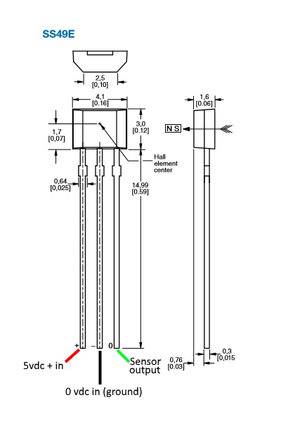
On a hall sensored throttle would probably be safest if you look to see ( or OHM) where the wires attach to...
If testing the wires coming from the controller...
Controller Wiring...
Note: the controller 5 vdc regulator is not very powerful and is only rated to provide around 100mA or even less.(I've seen down to 40 mA) Do not short out the supply wires. It will survive a brief short, which I unfortunately can attest too. But probably not for an extended period, which I decline to verify...
Insure correct battery power voltage to controller. Some controllers require an activation (key switch or button...) or "on" signal to it before energizing 5+vdc supply.
Start by checking the three wires for the 5+vdc regulated output power with a good quality multi-meter.
Mark the positive wire as 5 vdc +(Typically RED and reference color in this thread), Then using a DMM with high resolution and keeping the positive probe there...check the other two wires with the Black test lead, both will provide a grounding path, but the sensor wire has a little resistance in it. So true o vdc battery negative wire or ground will have the highest voltage potential. Mark it 0vdc or ground. (Typically Black and the reference color in this thread.) With the throttle sensor signal input wire, just a hair less voltage potential. Mark it signal input. (Typically Green or White, Green as the reference color in this thread.). Example: In my testing, from 5+vdc to true ground meter read 5.07 vdc. And to signal input wire, read 5.06 vdc.
To double check ground. Disconnect battery and allow capacitors to discharge. Then check resistance between negative battery connector connection and previously identified throttle ground, there should be NO resistance what so ever as it is a direct connection.
If you open up the controller and are able to see the PCB labels. Positive power wire for the throttle (5+vdc)will go to the terminal labeled SP5V. Negative or Ground wire (0vdc) will go to GND, and Sensor wire will go to SP.
As lifted from this thread...
https://electricbike.com/forum/foru...r-throttle-operation-testing-and-modification
docw009
1 MW
modaniel said:The throttle has 3 pins. How can I tell the polarity? Perhaps I can use a digital multimeter to do this?
Are we talking about the connector on the controller side or the throttle side? And what kind of connector is it?
I think I,m faced with similiar situation too.
modaniel , are you planning to keeping the original plug on the controller , or splicing into it or doing your splicing off the , throttle and brake plug ends then adapting new ways to connect everything together plz let us know and also
Doc said the 5th plug item coming off the branch is headlamp ,, definetly dont want to shrt any wires , it will incinerate pins instantly !!
What kind of controller ? modaniel
Similar threads
- Replies
- 4
- Views
- 130
- Replies
- 1
- Views
- 226