
I have a 500w rear hub motor off a 2020 Lectric XP. My motor stopped working after 80 miles. The motor is under warranty and Lectric is providing a new one. The motor is currently out of stock so I’m on hold for now. Lectric told me that the motor has a bad speed sensor. Being a lifelong DIY guy. I started researching and decided to pull it apart and replace the three hall sensors. Didn’t know how to test them so I replaced all three. Of course I wasn’t 100% sure which type of hall sensor I needed. Reading what I could find, I think the Honeywell bipolar that I got were right but that’s questionable. Anyway after replacing them it was still a no go. It’s possible that my soldering job to the circuit board is less than perfect but I don’t know for sure because I don’t know how exactly to test the hall sensor. I’ve looked on YouTube and yes I have a voltage meter but I’m not sure how to use it. I’ve found a diagnostic tool on Bolton ebikes for $30 that might be what I need but I’m hesitant because I’m not sure it’s applicable. None of my local bike shops want to touch it and at $80 an hour service charge I’m told it’s more cost effective to just buy a new motor. Lectric doesn’t sell their motor. And yes I’m getting a new one from my warranty. I’m rambling. I really don’t want this motor to go in the trash when I believe the fix for it is really very simple. Maybe That’s my misperception. Seeking enlightenment in Austin Texas.
You are using an out of date browser. It may not display this or other websites correctly.
You should upgrade or use an alternative browser.
You should upgrade or use an alternative browser.
500w rear hub motor bad speed sensor
- Thread starter Alan S
- Start date
Chalo
100 TW
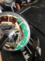
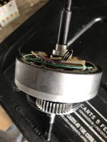
You can replace the Hall sensors. It is a very simple fix, but it can be a major nuisance. They're probably jammed into slots in the stator, and maybe glued in as well. You probably have to get the rotor out of there first, which is tricky to do without getting pinched or damaging your magnets.
Before you replace the Hall probes, fully inspect all the wires connected to the PCB, to be as certain as you can that there isn't a continuity or short circuit problem somewhere.
I'd desolder the old Halls from the board first, cut the ties holding the board down, then gently pull back the board to expose the Halls. If you can pluck them out with a pliers, good-- you lucked out. If you have to pry, crack, and scrape them out, just be careful not to nick any wires in the process. Sometimes I've had them pop right out; other times I've had to use a dental pick to remove adhesive and make clearance for the new ones.
Put the new Halls into their slots before you try to solder them to the board, so you know they'll fit correctly. Carefully lower the PCB down over the Hall leads, solder and trim, then tie everything back down the way you found it.
You have to be even more cautious getting the rotor back in than you were taking it out. It will bite you hard if you let it.
When you're done, you will have an appreciation for why it's cheaper to get a new motor than to fix the one you have.
TommyCat
10 kW
As far as testing goes... this thread gives good information on how to test the motor's hall sensors. Both while connected to the controller, or just alone on the bench. Testing for each is some what different.
https://electricbike.com/forum/foru...-motor-s-phase-wiring-hall-sensors-and-wiring
Regards,
T.C.
https://electricbike.com/forum/foru...-motor-s-phase-wiring-hall-sensors-and-wiring
Regards,
T.C.
Alan S said:Lectric told me that the motor has a bad speed sensor. Being a lifelong DIY guy. I started researching and decided to pull it apart and replace the three hall sensors. Didn’t know how to test them so I replaced all three.
If they really mean "speed sensor", then it isn't the three halls that are inserted into the stator laminations (which are actually position sensors in this case), it's the single one that comes up off the board on the three black wires, near the marking YY101. It is probably the same type as the others, which is usually a Honeywell SS41A or SS411A or a clone thereof.
To test it, you need to have the motor connected to the controller and the systme powered up, then put your voltmeter black wire on battery negative (or any system ground), and the vm red wire on the signal pin of the sensor, which should be the one closest to the last 1 in YY101. Since that sensor would read the magnet on the casing of the motor when it's assembled, you'll need to use a separate magnet (like on a namebadge, etc) and move it past the sensor while watching the meter. If it changes from around 0V to around 5V, and/or vice-versa, whenever the magnet passes, then the sensor works.
You can test the other ones the same way, though since the motor has magnets already you can just spin it slowly by hand.
First of all I want to thank you for identifying the speed sensor for me. I had no idea where it was. Here’s a pic of my Honeywell ss41a sensor next to the speed sensor I extracted with the black wires. The sensor head on the speed sensor looks to be the same size as the ss41 but the wires a obviously very different. You can see from the pic the black wires with the rubber insulation peeled away are copper colored. Since the speed sensor looks so different from the hall sensor I want to say they are not the same. What are your thoughts? And Do you have any idea where I might purchase a speed sensor like this one?
Attachments
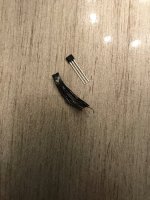
To find out where to buy one just like it you'd need to read the numbers off the face of it, and then find that one at an electronics supplier like Mouser or Digikey, etc. They can help you find the right part, in most cases. My guess is that the ss41a will directly replace it...but you won't know for sure till you fidn out what the original is.Alan S said:Here’s a pic of my Honeywell ss41a sensor next to the speed sensor I extracted with the black wires. The sensor head on the speed sensor looks to be the same size as the ss41 but the wires a obviously very different. You can see from the pic the black wires with the rubber insulation peeled away are copper colored. Since the speed sensor looks so different from the hall sensor I want to say they are not the same. What are your thoughts? And Do you have any idea where I might purchase a speed sensor like this one?
But...before taking parts out of the motor and replacing them, you need to *test* them as described to be sure they are actually the problem. Otherwise you not only don't fix the problem (if they weren't bad) but add the potential for new problems that then complicate troubleshooting the original problem.
If you like you can just replace parts until it works or you run out of parts to replace, but it's not a very efficient way of doing it.
")
The reason the wires look so different is that the motor maker put heatshrink or other insulation over the bare part leads, after first soldering some extension wires, probalby solid small-guage copper, to them so that the sensor would end up in the right spot to meet the magnet on the motor housing. The leads on your new sensor are...new, and bare.
Most hall sensors that are thru-hole (PTH) type components, like the ones in most motors, will look exactly alike because they follow a standard for parts manufacture. It's a fairly deep subject, but you can start here
https://en.wikipedia.org/wiki/List_of_integrated_circuit_packaging_types#Transistor,_diode,_small-pin-count_IC_packages
if you want to learn about that sort of thing. The common hall package is the TO-92 "flat" style.
honeybadger_88
1 µW
- Joined
- Nov 2, 2022
- Messages
- 2
amberwolf said:Alan S said:Lectric told me that the motor has a bad speed sensor. Being a lifelong DIY guy. I started researching and decided to pull it apart and replace the three hall sensors. Didn’t know how to test them so I replaced all three.
If they really mean "speed sensor", then it isn't the three halls that are inserted into the stator laminations (which are actually position sensors in this case), it's the single one that comes up off the board on the three black wires, near the marking YY101. It is probably the same type as the others, which is usually a Honeywell SS41A or SS411A or a clone thereof.
To test it, you need to have the motor connected to the controller and the systme powered up, then put your voltmeter black wire on battery negative (or any system ground), and the vm red wire on the signal pin of the sensor, which should be the one closest to the last 1 in YY101. Since that sensor would read the magnet on the casing of the motor when it's assembled, you'll need to use a separate magnet (like on a namebadge, etc) and move it past the sensor while watching the meter. If it changes from around 0V to around 5V, and/or vice-versa, whenever the magnet passes, then the sensor works.
You can test the other ones the same way, though since the motor has magnets already you can just spin it slowly by hand.
@amberwolf: I came over this post just now googling how to install hall speed sensor (with not too much luck but this). You write that the sensor would "read the magnet on the casing of the motor" - how does this work in practice? Won't the casing and the sensor move together? And how would I typically locate this magnet? I'm not sure if I've pulled the hall long enough inwards and might need to extend it, at least comparing to the picture in this post...
honeybadger_88
1 µW
- Joined
- Nov 2, 2022
- Messages
- 2
honeybadger_88 said:amberwolf said:Alan S said:Lectric told me that the motor has a bad speed sensor. Being a lifelong DIY guy. I started researching and decided to pull it apart and replace the three hall sensors. Didn’t know how to test them so I replaced all three.
If they really mean "speed sensor", then it isn't the three halls that are inserted into the stator laminations (which are actually position sensors in this case), it's the single one that comes up off the board on the three black wires, near the marking YY101. It is probably the same type as the others, which is usually a Honeywell SS41A or SS411A or a clone thereof.
To test it, you need to have the motor connected to the controller and the systme powered up, then put your voltmeter black wire on battery negative (or any system ground), and the vm red wire on the signal pin of the sensor, which should be the one closest to the last 1 in YY101. Since that sensor would read the magnet on the casing of the motor when it's assembled, you'll need to use a separate magnet (like on a namebadge, etc) and move it past the sensor while watching the meter. If it changes from around 0V to around 5V, and/or vice-versa, whenever the magnet passes, then the sensor works.
You can test the other ones the same way, though since the motor has magnets already you can just spin it slowly by hand.
@amberwolf: I came over this post just now googling how to install hall speed sensor (with not too much luck but this). You write that the sensor would "read the magnet on the casing of the motor" - how does this work in practice? Won't the casing and the sensor move together? And how would I typically locate this magnet? I'm not sure if I've pulled the hall long enough inwards and might need to extend it, at least comparing to the picture in this post...
Never mind, realized just now which metal (the casing, not the center "flange") you were referring to and found that indeed there is a magnet on the outer casing cover - so I just need to extend the sensor outwards to reach this. Thanks though!
Similar threads
- Replies
- 3
- Views
- 153
- Replies
- 7
- Views
- 291