Turn signals shared between 2 batteries

Reflector

10 W
Joined
Jun 7, 2014
Messages
80
Location
Land of The Great Grey Grasshopper
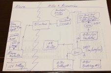
I want to share my turn signals between the batteries of;
1) an alarm system
2) my 12V velomobile supply (lights, horn, fan and turn signals)

When my (48) motor supply is turned off, there is no feed to the 48V / 12V buck converter which then feeds the supply (in #2 above).

To share the signals between both electrical systems, would I just need to install diodes at appropriate places or would e.g. using the SPST switch in the diagram do the trick to prevent possible accidental voltage feedback?

PS
turn signals = blinkers = indicators
 

Attachments

  • blinkers flow chart.jpg
    blinkers flow chart.jpg
    177.7 KB · Views: 255
I think you need to feed the bulbs via diodes. At least, that's how I would do it. Have to choose bulbs/LED's that won't care much about the 1/2 to 1V drop across the diode.

If you don't want to research the right diode, trailer lights often have diodes. Pre built modules like this:

https://www.amazon.com/Hopkins-48955-Towed-Vehicle-Diodes/dp/B0002Q81Y4
 
Diodes are the simplest way to do it. The kit BlueSeas linked above would do it.

If you want something smaller, you could probably use 1N4001 (low current) or 1N5401 (higher current, up to 3A) individual diodes wired inline with your cabling and heatshrunk to insulate them.

There are higher current axial-lead diodes, but they get bigger fairly rapidly from there. One of the limitations is how rapidly heat can be removed from them at higher currents, so thinner heatshrink is better for that, though not as good at electrical insulation / preventing abrasion damage.
 
Oh, ok guys now I think I understand. The diode has 2 inputs (from alarm and from 12V bus) and the output goes to the +ve of the LED indicator. Then repeat the procedure for the remaining 3 indicators. Have I got it?
 
Reflector said:
Oh, ok guys now I think I understand. The diode has 2 inputs (from alarm and from 12V bus) and the output goes to the +ve of the LED indicator. Then repeat the procedure for the remaining 3 indicators. Have I got it?

That doesn't sound right to me.

First though, the 1N4004 will likely work if the bulb draws less than 1A. Otherwise you need a bigger diode.

Now, for the wiring, you probably need 3 possibly 4 diodes. They are one way devices. Current can only flow from the input to the output, but not in reverse. Test this with a multimeter to verify.

The turn signal outputs each need a diode. The blinker likely wants to flash both turn bulbs. You can use a single diode, if the current requirements of both bulbs is under the rating of the diode. If not, you need a 4th diode. The output of the diodes feeds the ungrounded B+ side of the bulb.

Hope that helps!
 
Reflector said:
Oh, ok guys now I think I understand. The diode has 2 inputs (from alarm and from 12V bus) and the output goes to the +ve of the LED indicator. Then repeat the procedure for the remaining 3 indicators. Have I got it?
Sounds right, if you mean the diode units BlueSeas linked, that have two input pins.

If you're using the 1N4004 diodes, you have to connect two diodes in a "Y", to make something that does what one of those modules does.

Whether you connect the ends with the bands on them, or hte ends without, depends on whether the lights are supplied with +12v to turn them on (wiht ground always present) or if they are grounded to turn them on (with 12v always present).

If 12v is used to turn them on, then the diode Ys will be made by connecting the ends with the bands together, and that end goes to the 12v input of one pair of lights. (because presumably both your left lights would come on together at minimum, or both your right lights). If ground is used to turn them on, then you connect the ends without bands.

As long as the total current two lights use is less than 1A, then you can use these diodes. If it's more than 1A but less than 2A, you can parallel pairs of diodes instead of using single ones to make the Ys.
 
I've got German LED velomobile indicators installed which ran okay via the Zippy hard pack 5,000mAh LiPo. If I use the diodes I have on hand it looks like I'd need one pair (in 'Y' formation) per indicator. Now I've realised that I'd also have to run separate wiring to the indicators from each battery. With everything already zipped up in the back of the velomobile and all the wiring runs contained in a 7 core tinned cable, I'll have to shelve the idea of my alarm flashing the lights.
It was worth a try and thanks for all of your input.
 
No, you don't need to run separate wiring to the lights. You put hte diodes at wherever the blinker is right now, as that's the source to reach them. If the blinker output wiring is split to go to each set then you just put the diodes right there at the splits with the bottom of the Y (common end) to the lights, and the blinker to one of the top Y arms. Then connect all the other top Y arms together, and add the wiring from the alarm to that since it's going to blink them all together.
 
Back
Top