Mac motor build help!

Makelele

1 mW
Joined
Feb 23, 2021
Messages
10
Hello everybody!

Im building ebike with mac motor(clone propably) and i'd like to ask some help if there is someone Who knows about this.

I got this motor cheap because last owner tried to hook it up with asi bac 800 controller but it wasnt successful. Problem was that the controller needed to be reprogrammed for the motor. I tryed to program it myself with ttl to bluetooth module but could not get it to work. I even got 2 week access for the bacdoor mobile app but could not get it to connect. It was too much for me and decided to buy cheap KT controller.

Now the motor has 5 hall sensor wires and the controller has 6 with one white extra wire. What should i do with it? Leave the white wire off or buy another controller again?

Also the motor has another 2 wire connector with white and gray wires and i have no idea what those are? Speed or temperature? My KT controller has no place for it. I'll try to attach pictures for you to see.
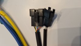
16141568860029201384060319846473.jpg

Thanks in advance!
 
Makelele said:
Now the motor has 5 hall sensor wires and the controller has 6 with one white extra wire. What should i do with it? Leave the white wire off or buy another controller again?
It's probably either for a temperature senosr or a speed sensor. If your motor doesn't have one, then you just leave it unconnected. You'd need to check the manual or connection guide from the specific place you bought your controller from to find out which one that is for, or else experiment. (sometimes opening up the controller may show a marking on the pad it goes to that helps figure it out, and sometimes the marking is just cryptic).


Also the motor has another 2 wire connector with white and gray wires and i have no idea what those are? Speed or temperature?
If it's a speed sensor, then with two wires it would have to be a reed switch, which is unlikely. But you can test for that with a multimeter set to continuity or the 2ohm range, and put the meter leads on the pins, then manually spin the wheel (either way, for a speed sensor; if testing halls you have to spin it backwards). If the reading changes periodically as the wheel spins, it's a speed sensor. If it is a speed sensor, then you can hook one of the wires to ground, and the other to the speed input wire of the controller (if it has one).

If it doesn't change, then change the meter's setting to 200kohms, and note down the reading. Move the motor to a place that is significantly warmer or cooler and leave it for an hour, then retest. If the reading changes by some amount, it is a temperature sensor. If it is a temperature sensor, then you can hook one of the wires to ground (usually; sometimes it goes to 5v) and the other to the temperature sensor input of the controller (if it has one). Some of them have a polarity, and some do not. If it doesnt' work one way, swap the wires. Note that for it to give a useful temperature reading the kind of sensor that is in the mtoro has to be matched to the setting in the controller for which sensor is being read, if it has sucha setting (some don't, and will only correctly read one specific sensor type and model).
 
Thank you for the help!

I got document for the controller and the white wire is indeed speed sensor. So now i just hope that the motors white and gray wires are speed sensor also so i can hook it up. And thank you for the detailed testing methods. I will do them and get back after.

Thanks again!
 
I have a MAC 12t running on a 35a KT controller. I consider it a great setup! The KT "imitation torque control" is chinglish for "power based" cadence system that's a joy to ride!

The white wire coming from the motor is the speed sensor - but it's useless as there's no signal unless the motor is running. For a full time speedo, you'll need an external speed sensor (magnet on spoke set up works fine) and use the output from that to the KT white wire.

I know the MAC's have a temp sensor option, so my guess at the extra 2 wires would be for that
 
Hey nice to hear you have same kind a setup.

If i can ask some more dumb questions from you all i'll aprreciate much.

I was trying to test my motor so i hooked up all the wires from motor to controller expect the white and gray(temp propably) and i put thumb throttle (white black red) to controllers(blue black red) and i tried to spin the wheel with throttle but nothing happens. My display shows voltage and temperature so its getting power but the throttle does nothing right now. Do i need to hook up all wires like brakes and pas and all that?
 
The 3 phase wires from the controller need to fire the motor phase wires in the correct order, otherwise you'll have either nothing like you have, or you'll have some weird buzzing or jerking when you apply power.

KT has sensored and sensorless controllers, so depending on which you have you may have to have the 3 small hall sensor wires (whose colors will match the order the phase wires are connected).

From my notes. With ANY luck this should work for what you have to do. Best of luck!

Phase Firing order    Motor    Controller     
A                    Blue          Yellow           
B                    Green        Blue           
C                    Yellow       Green 

Hall sensors fire in the same order, so they match the phase motor/controller color sequence  
 
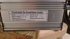
I dont know if i have sensored or sensorless. They didnt tell in item description. Is there any signs to spot the difference? I'll put picture of the
controller

20210227_212431.jpg

I tried 6 different combinaitions for the phase wires and got nothing :( should i switch hall sensors also as i switch around with phase wires?
 
Oh you told me that sensor wires go like phase wires sorry :roll: i have to get some better connector for them so that they'll be easy to switch around. Now i have them soldered color to color so guess thats why i dont got nothing from the motor
 
Okay so the pas sensor needed to be active to be able to use throttle. I got it spinning now!

Should i try all the different combination on phase wires and see how many watts it draws from motor with no load? And the smallest wattage is the right position? Or how its done correctly?
 
If it seems to be working OK, with good power right from stopped, you're most likely good to go. No point in looking for trouble!
 
Yeah i was on a first ride today :D . Pas didnt work so i need to look those wires again.

And the speed limit from the display was set on 72 km/h and it hit that allmost instantly and i wasnt going 72 more like 25-30km/h max and it drawed 700-800 watts on a straight road and little bit over 1000w on small up climb. Need to check speed with gps. But it did accerelate pretty damn good.

Wondering how to get the speedo on display show accurate speeds?
 
Sounds like you're on your way. Holler if you can't figure something out after looking through the manual.
 
So im using ktlcd8h display and im stuck on p1 and p2 setting. Everything else seems basic.

I dont know my motors gear reduction ratio or how many magnet poles it has. I contacted the manufacturer but if they cant tell could you share your settings or if you know your motors specs maybe share those and i can try to figure right settings

Many thanks again your'e a legend AHicks!
 
P1 and P2 are about your speedometer. P1 one is the calibration for speed. I had to mess with this quite a bit, as I had to set it 3-4 times to match my wife's bike's speed, which I knew was accurate. Start with the suggested 192 and go from there.

On P2, this is getting back to what I was mentioning regarding an external speed sensor (magnet on spoke). It should work when set to 1, but my bet is the speedo is going to go to 0 when you are coasting.
 
Back
Top