Hi everyone,
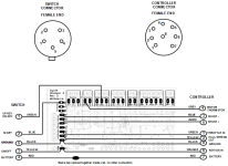
I have a question about the new CA3-WP with MFSwitch.
https://ebikes.ca/shop/electric-bicycle-parts/cycle-analysts/ca3-wp-and-mfswitch.html
I can't find any wiring diagram for this new cycle analyst, especially about the aux input.
So here are my interrogations:
- What about the regular aux input cable? Is it still there? If yes, is it connected to the same location on the electronic board?
- What about the possibility with the MFswitch version to add a 3 position switch? A potentiometer?
Thank you for your support")
I have a question about the new CA3-WP with MFSwitch.
https://ebikes.ca/shop/electric-bicycle-parts/cycle-analysts/ca3-wp-and-mfswitch.html
I can't find any wiring diagram for this new cycle analyst, especially about the aux input.
So here are my interrogations:
- What about the regular aux input cable? Is it still there? If yes, is it connected to the same location on the electronic board?
- What about the possibility with the MFswitch version to add a 3 position switch? A potentiometer?
Thank you for your support