LewTwo
1 MW
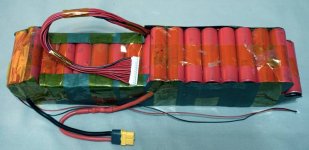
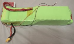
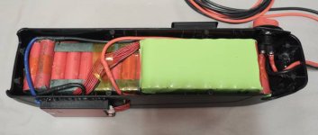
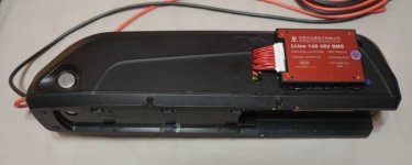
Shark Battery Pack died last summer and I am finally getting 'round-to-it" rebuilding it. BMS would not longer charge or deliver power. All cell strings are in ballance (go figure).
Cells: 14S4P Panasonic-Sanyo NCR18650GA (these are LiNiCoAlO2 cells)
Nominal Voltage: 14x3.6 = 50 Volts
Nominal Capacity: 4x3300mAh = 13.2 Ahr
Motor is a Golden Motor front hub Smart-Pie V4 which should be:
(FYI for those that do not know, the controller is built into the motor)
Open Voltage: 20-60 Volts
Rated Power: 200-400 watts
Continuous Current: 18 Amp
Max Phase current: 50 Amp
Best I can remember I have never gone over 1200 watts ... maybe never over 1000 watts ... senility is setting in.
I am trying to get all my ducks lined up for the rebuild. I have a new common port DALY 14S Li-Ion with ballance (simple version, no bluetooth, fans, etc): 1-101-14460-J15C FK05. This one is rated for max 15 Amp charge current and max 30 Amp discharge current. Two things to note about the BMS. It will NOT fit in the shark's heat sink as I had hoped. Second the balance lead pin spacing is 2.0mm (as opposed to the 2.54mm spacing of the existing balance leads connector). So I must replace the balance leads --- no big deal.
The existing pack has no fuse. I am thinking it might be wise to add one while I am at it. High voltage DC fuses are about as common as hens' teeth. What I have found is OptiFuse 58 Volt ATC/ATO blade fuses: https://www.optifuse.com/blog/p091102.php
Not available via my prefered source (Amazon) so next up is Digikey (with associated high shipping cost). I am also getting OptiFuse inline 12 AWG 32 Volt fuse holders (red for the positive lead). I have ordered 20, 25 and 30 Amp fuses thinking that 20 amp will be the optimum. Question: Am I on the right path here or am I missing something obvious
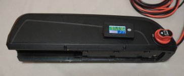
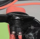
The existing pack has a useless LED power gauge and external charge port. Both will be removed and the holes blanked.
The pack was originally wrapped with cardboard, dabbled with silicon glue and lashed with fiberglass shipping tape. I plan to use 210mm (flat) heat shrink tubing. Internally I am think of using 4mm gold plated bullet connectors for the power leads rather than hard soldering. From what I have been able to find on the RC forums they should be able to handle the current .... up to about 30 Amps anyway. Comments

I smoked the stab connector during disassembly. I purchased a XT90 anti spark connector (because it was there). When I got it, I had to use two pairs of pliers and a lot of effort to separate the male from the female side ... 'tis a bit better now but not something I want to do repeatedly. I am thinking of attaching the female side to the actual pack and putting the Male connector in the mount. Then poke 'em down into the cavity of the Shark mount. FYI: I do not remove the battery on a regular basis anyway. Comments
The external power cable will have an XT60 connector (female this time). With the common port BMS it will be used for both power to the system and alternately for charging.
I am thinking of adding a XT60 configured as a 'arming conector' to the Shark mounting base. I was going to use the XT90 antispark for this purpose but the darn thing is too hard to remove.
Shirley I have missed something
Cells: 14S4P Panasonic-Sanyo NCR18650GA (these are LiNiCoAlO2 cells)
Nominal Voltage: 14x3.6 = 50 Volts
Nominal Capacity: 4x3300mAh = 13.2 Ahr
Motor is a Golden Motor front hub Smart-Pie V4 which should be:
(FYI for those that do not know, the controller is built into the motor)
Open Voltage: 20-60 Volts
Rated Power: 200-400 watts
Continuous Current: 18 Amp
Max Phase current: 50 Amp
Best I can remember I have never gone over 1200 watts ... maybe never over 1000 watts ... senility is setting in.
I am trying to get all my ducks lined up for the rebuild. I have a new common port DALY 14S Li-Ion with ballance (simple version, no bluetooth, fans, etc): 1-101-14460-J15C FK05. This one is rated for max 15 Amp charge current and max 30 Amp discharge current. Two things to note about the BMS. It will NOT fit in the shark's heat sink as I had hoped. Second the balance lead pin spacing is 2.0mm (as opposed to the 2.54mm spacing of the existing balance leads connector). So I must replace the balance leads --- no big deal.
The existing pack has no fuse. I am thinking it might be wise to add one while I am at it. High voltage DC fuses are about as common as hens' teeth. What I have found is OptiFuse 58 Volt ATC/ATO blade fuses: https://www.optifuse.com/blog/p091102.php
Not available via my prefered source (Amazon) so next up is Digikey (with associated high shipping cost). I am also getting OptiFuse inline 12 AWG 32 Volt fuse holders (red for the positive lead). I have ordered 20, 25 and 30 Amp fuses thinking that 20 amp will be the optimum. Question: Am I on the right path here or am I missing something obvious
The existing pack has a useless LED power gauge and external charge port. Both will be removed and the holes blanked.
The pack was originally wrapped with cardboard, dabbled with silicon glue and lashed with fiberglass shipping tape. I plan to use 210mm (flat) heat shrink tubing. Internally I am think of using 4mm gold plated bullet connectors for the power leads rather than hard soldering. From what I have been able to find on the RC forums they should be able to handle the current .... up to about 30 Amps anyway. Comments

I smoked the stab connector during disassembly. I purchased a XT90 anti spark connector (because it was there). When I got it, I had to use two pairs of pliers and a lot of effort to separate the male from the female side ... 'tis a bit better now but not something I want to do repeatedly. I am thinking of attaching the female side to the actual pack and putting the Male connector in the mount. Then poke 'em down into the cavity of the Shark mount. FYI: I do not remove the battery on a regular basis anyway. Comments
The external power cable will have an XT60 connector (female this time). With the common port BMS it will be used for both power to the system and alternately for charging.
I am thinking of adding a XT60 configured as a 'arming conector' to the Shark mounting base. I was going to use the XT90 antispark for this purpose but the darn thing is too hard to remove.
Shirley I have missed something


