Hello people,
I have a rather special question regarding electrical engineering:
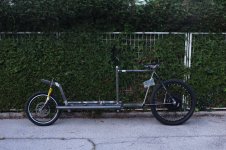
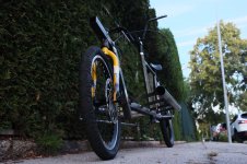
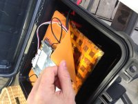
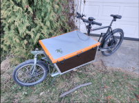
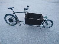
Two years ago i welded a Long John style cargo bike together, build myself a 13s9p VTC6 Battery Pack safely controlled by a lithiumbatterypcb BMS and hooked the thing up with a Kelly KLS7212S to a MXUS 3k Turbo 5t.
The bike is riding like a charm and i haven't had any problems since.
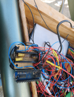
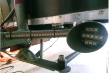
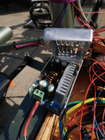
But i didn't want to stop there, so i added a lighting system based on a Arduino nano. It drives two power Led's as headlights (harvested from headlamps and build into the frame tubes) as well as a strip of 80 ws2812b LED's at the back of the cargo frame which enables me to display a back-light, brake-light as well as turn signals. The whole lighting system is consuming around 50W at full light and braking. This is the reason why I power it with a cheap but beefy DCDC step-down from Aliexpress that is rated for 15A 200W and 60V. ( https://www.aliexpress.com/item/32970433581.html?spm=a2g0s.9042311.0.0.26be4c4d4dsDu0 )
The stepdown is hooked up in parallel between the battery and the motorcontroller and provides the Arduino and LED's with the required 5V.
After a year of flawless riding the following problem occurred:
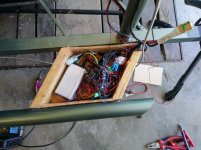
I charged my battery-pack completely over night and started riding down a little hill the next morning. When i started using the brake, i recognized a little pop and smoke coming out of the electronic box.
I immediately disconnected the battery and realized that the whole 5V circuit was fried. The caps from the Stepdown exploded, the fuses from the Arduino were blown as well and that not being enough, every single one of the 82 LED's were burned through as well.
My guess for the reason of the whole fiasco is, that the battery was so fully charged, that the BMS closed to protect from overcharging and the generated power from the braking didn't had anywhere else to go. Is this conclusion realistic?
Does somebody have another answer to why I had the problem?
I found the following possibilities to protect the stepdown and in conclusion my 5 V circuit in the future:
Thanks in advance for any helping advices and i hope i didn't screw up big time with my first post in this forum.
Some pics of the project are attached,
all the best,
WALI
I have a rather special question regarding electrical engineering:
Two years ago i welded a Long John style cargo bike together, build myself a 13s9p VTC6 Battery Pack safely controlled by a lithiumbatterypcb BMS and hooked the thing up with a Kelly KLS7212S to a MXUS 3k Turbo 5t.
The bike is riding like a charm and i haven't had any problems since.
But i didn't want to stop there, so i added a lighting system based on a Arduino nano. It drives two power Led's as headlights (harvested from headlamps and build into the frame tubes) as well as a strip of 80 ws2812b LED's at the back of the cargo frame which enables me to display a back-light, brake-light as well as turn signals. The whole lighting system is consuming around 50W at full light and braking. This is the reason why I power it with a cheap but beefy DCDC step-down from Aliexpress that is rated for 15A 200W and 60V. ( https://www.aliexpress.com/item/32970433581.html?spm=a2g0s.9042311.0.0.26be4c4d4dsDu0 )
The stepdown is hooked up in parallel between the battery and the motorcontroller and provides the Arduino and LED's with the required 5V.
After a year of flawless riding the following problem occurred:
I charged my battery-pack completely over night and started riding down a little hill the next morning. When i started using the brake, i recognized a little pop and smoke coming out of the electronic box.
I immediately disconnected the battery and realized that the whole 5V circuit was fried. The caps from the Stepdown exploded, the fuses from the Arduino were blown as well and that not being enough, every single one of the 82 LED's were burned through as well.
My guess for the reason of the whole fiasco is, that the battery was so fully charged, that the BMS closed to protect from overcharging and the generated power from the braking didn't had anywhere else to go. Is this conclusion realistic?
Does somebody have another answer to why I had the problem?
I found the following possibilities to protect the stepdown and in conclusion my 5 V circuit in the future:
- Crowbar circuit
- Zener-Diod with fuse
- some fancy comparator circuit that requires a steady voltage that i can maybe get from the kelly controller?
- regulating the input of the Stepdown with a power MOSFET controlled by the arduino that senses the voltage
Thanks in advance for any helping advices and i hope i didn't screw up big time with my first post in this forum.
Some pics of the project are attached,
all the best,
WALI
Attachments
-
 Capture.JPG257.6 KB · Views: 540
 -
 DSCF4988.JPG348 KB · Views: 540
 -
 DSCF5509.JPG561.3 KB · Views: 540
 -
 DSCF5514.JPG381.6 KB · Views: 540
 -
 IMG_7942.JPG354.9 KB · Views: 540
 -
 IMG_8075.JPG513.7 KB · Views: 540
 -
 plane.PNG584.2 KB · Views: 540
 -
 blowncaps.PNG270.1 KB · Views: 540
 -
 blownled.PNG396.4 KB · Views: 540
 -
 side.jpg403.7 KB · Views: 540
 -
 blownstepdown.PNG260.2 KB · Views: 540
")