Standard phasing/color coding question

JackFlorey

100 kW
Joined
Feb 19, 2020
Messages
1,575
Location
San Diego
Hey all. I have a Radcity bike here and I'm replacing the controller to see what I can get out of the motor. Does anyone have something like a scope plot that shows the "standard" phasing for three phase sensored motors? i.e. this is what the voltages look like on the three phases vs this is what the voltages look like on the Hall sensor outputs when you spin the wheel, no load.

Also does that correspond to any sort of standard color scheme? I've seen yellow-green-blue for phase wires, and red-black for Hall power, but the three sensor wires seem to vary widely in color.

(The bike uses the Julet Z916 motor connector but I can't find any standard pinouts for that.)
 
You may be able to get some assistance from Alan B, since it looks like he's done a controller sway already:

https://endless-sphere.com/forums/viewtopic.php?f=3&t=102321&p=1565383&hilit=controller#p1565383
 
JackFlorey said:
Does anyone have something like a scope plot that shows the "standard" phasing for three phase sensored motors?
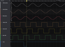
OK looks like no one does, so I did it myself.

Plot below. Top three are the phase connections themselves. They are all connected to ground via 220 ohm resistors to provide a ground reference.
Next three are Hall sensor outputs. Last one is a tach output (usually not present on most hubmotors since you can get the same info from the Hall output.)

Note that the Hall sensors output line up almost perfectly with the phase signal. There's a ~4% delay (compared to the entire period) in the Hall sensor output; it lags behind the phase output zero cross by about 4% of the entire period of the phase. Since Hall sensors are pretty fast I assume this is due to physical placement offset rather than actual delay in the electronics.

This makes it pretty easy to figure out how to connect sensors - match the sensor phase to the actual phase signal when spinning the wheel without a controller attached. In my case one side had all the colors identified, but even if the cabling is different this relationship should hold.

Note that the phase advance is "backwards" in my plot; the wheel was being spun forward but the "last" (blue) phase appeared first in sequence. This is just an artifact of what color you assign to what phase; if you decide that blue-green-yellow is the order you want to use it would look like the phases were advancing "forward."

I'm going to leave this here as a reference, so that in four years when I am faced with another mystery motor I can refer back to this.
 

Attachments

  • BLDC_cap.PNG
    BLDC_cap.PNG
    22.9 KB · Views: 83
Back
Top