JackFlorey
100 kW
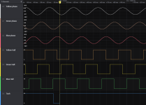
Hey all. I have a Radcity bike here and I'm replacing the controller to see what I can get out of the motor. Does anyone have something like a scope plot that shows the "standard" phasing for three phase sensored motors? i.e. this is what the voltages look like on the three phases vs this is what the voltages look like on the Hall sensor outputs when you spin the wheel, no load.
Also does that correspond to any sort of standard color scheme? I've seen yellow-green-blue for phase wires, and red-black for Hall power, but the three sensor wires seem to vary widely in color.
(The bike uses the Julet Z916 motor connector but I can't find any standard pinouts for that.)
Also does that correspond to any sort of standard color scheme? I've seen yellow-green-blue for phase wires, and red-black for Hall power, but the three sensor wires seem to vary widely in color.
(The bike uses the Julet Z916 motor connector but I can't find any standard pinouts for that.)