monkmartinez
1 mW
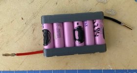
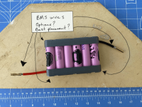
I am humbly asking for assistance, opinions and guidance in wiring a new BMS to the pack I am building. Each P-cell has a 9.5mm braid that runs underneath the 3d printed holder pictured below. Each cell has positive and negative 12AWG wire that will be soldered to the braid and then terminated with 4mm bullet connector. I haven't completed (heat shrink/strain relief) the individual 6p cells as I would like some ideas as to where to place the BMS leads.

From what I understand, I need to place the leads on the positive side of the P-cells. In my case, do you think it would be best to solder the leads to the wire at the bullet connector or closer the braid?

Disregard the negative side connections, as I made a mistake on that.
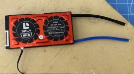
I am going to use a Daly BMS pictured below:

I am not sure if I should use XT60 or 4mm bullets for connecting the pack to the BMS and charger. Opinions on that?
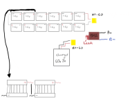
Here is an overall diagram I am drawing up to guide the final push for construction:

I will finalize and submit for comment before I actually power this thing up. My charger setup is completely configurable from 5v to 60v and 0.1ma to 6amp.

From what I understand, I need to place the leads on the positive side of the P-cells. In my case, do you think it would be best to solder the leads to the wire at the bullet connector or closer the braid?

Disregard the negative side connections, as I made a mistake on that.
I am going to use a Daly BMS pictured below:

I am not sure if I should use XT60 or 4mm bullets for connecting the pack to the BMS and charger. Opinions on that?
Here is an overall diagram I am drawing up to guide the final push for construction:

I will finalize and submit for comment before I actually power this thing up. My charger setup is completely configurable from 5v to 60v and 0.1ma to 6amp.

