How to make push button as throttle? +video

JonathanRS

10 µW
Joined
Jul 20, 2021
Messages
5
Hello, I recently decided to buy a 36v 250w ebike kit for my bicycle, the thing is that in my country it is illegal to use the accelerator and I had thought of putting a "horn" button but actually being a throttle to go unnoticed

What I did was connect to the positive switch of the throttle cable and the signal cable, but this happens, the first time I press it, it works but if I release the button and press it again, it stops working until I turn off and on again ebike kit , then it works again, one time only

Anyone knows how to solve this? Thank you!

Sorry for my bad english

[youtube]2iiftR7dfXI[/youtube]

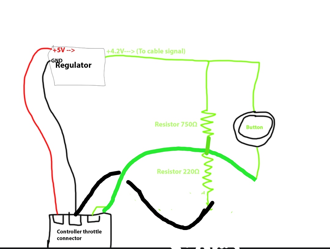
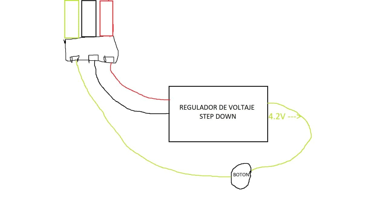
I have installed a reduced voltage because I understood that I had to regulate it to 4.2V, but I really do not know what voltage it is set to since I do not have a tool for this xD, but the strange thing is that the first time it works and the second time I pulse the button no

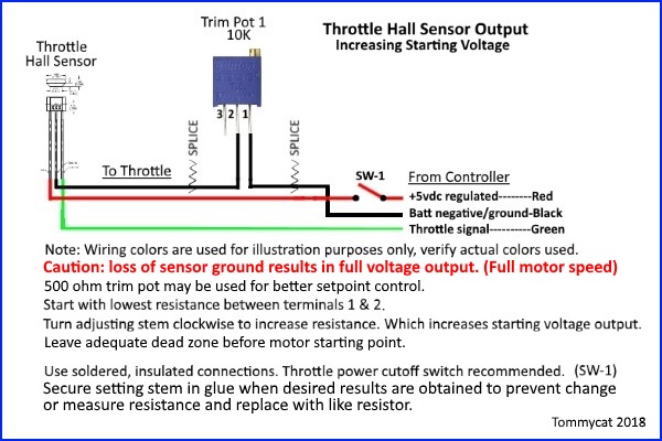
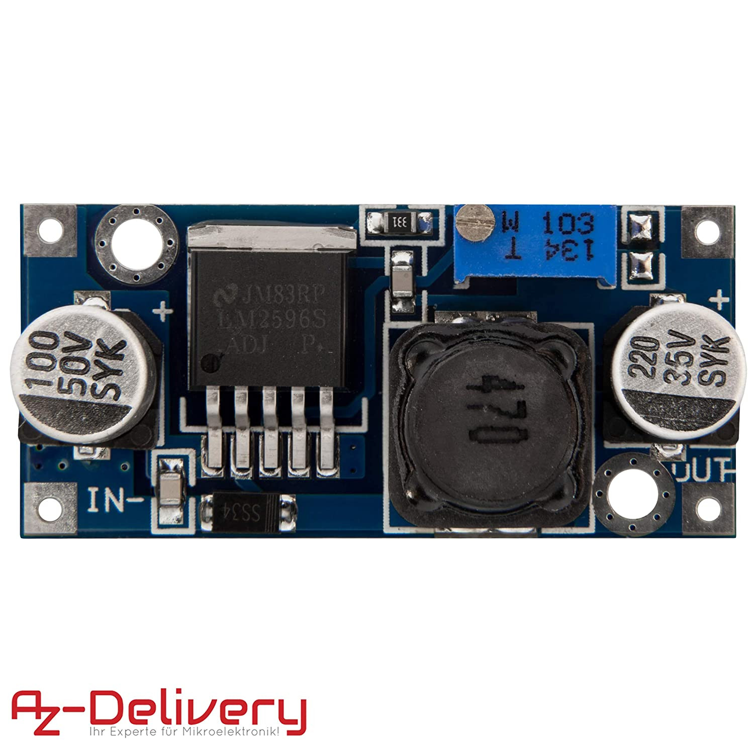
This is what I use to lower the voltage
fetch


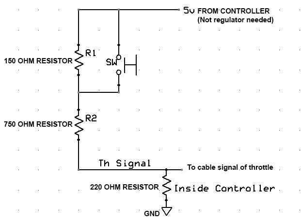
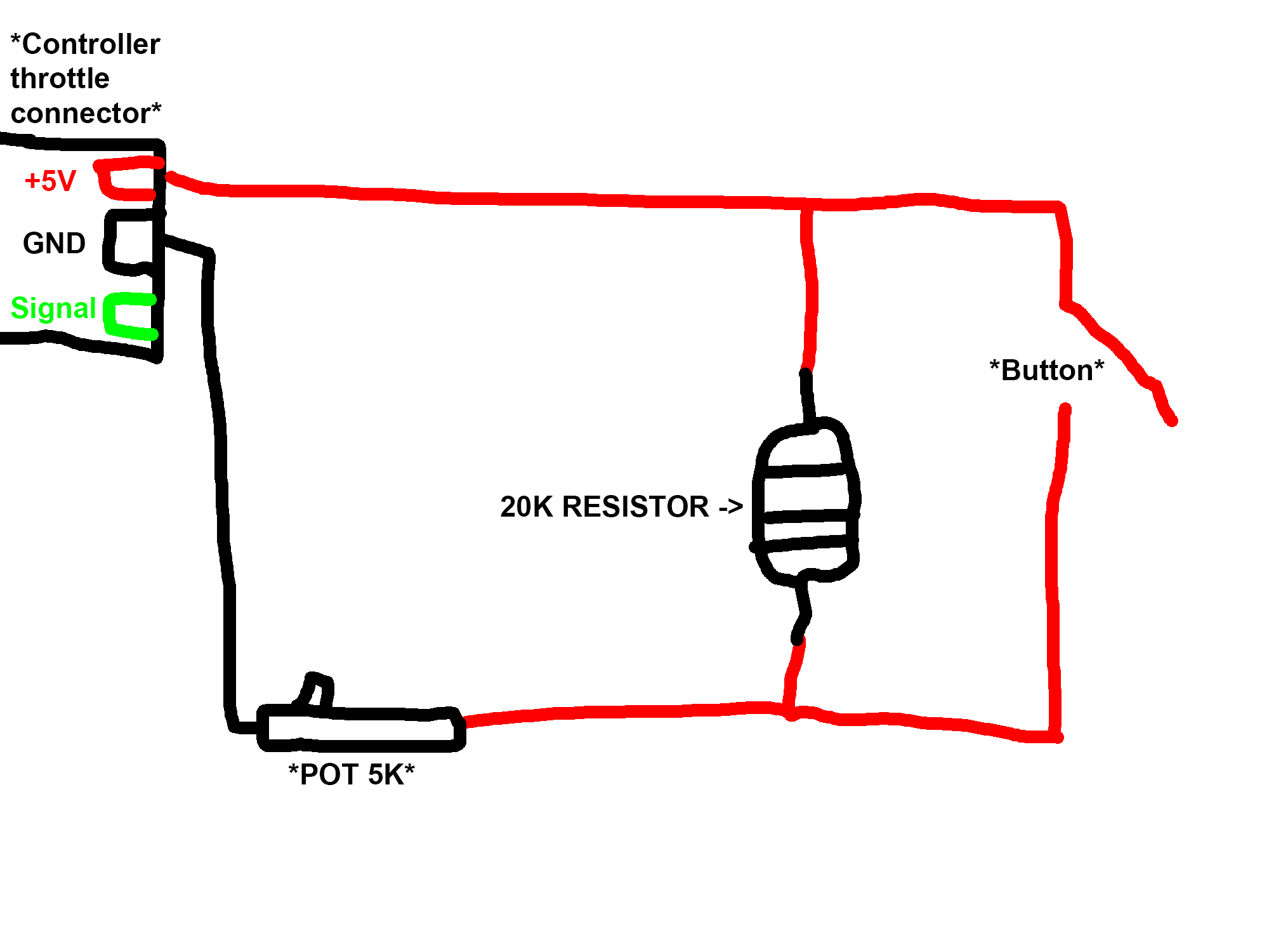
And this is the circuit
fetch
 
Ok, I understand that the throttle at rest marks 0.8V, so maybe that's why it fails, I have thought about making this circuit with resistors, how do you see it?

zVEcnfV.jpeg
 
Yes, you need the throttle signal to stay between 0.8v and about 4.0v. Your circuit might work if you use the right resistors. The correct value will depend on your controller. If you have a voltmeter, you can change the resistor values until you see the right range. My guess is you need much larger resistor values to have it rest at 0.8v.

If you turn everything off and use an ohmmeter to measure resistance between the throttle ground and signal lines going to the controller, it may be possible to calculate the correct resistor values. You could also use a resistor instead of a voltage regulator board. You could also make it work with just two wires.

pushbutton throttle.JPG
 
I use a variation of this circuit, setting the pot to the throttle level I want, and a switch to invoke the circuit (I also have a throttle). I use mine set at a very low throttle level (e.g. 100W) since I use mine for freewheeling, but you can set the pot to any level up to full throttle. Not as fancy as using a voltage regulator, so maybe to simple for your needs?
wfGeHkI.jpeg


https://electricbike.com/forum/forum/kits/golden-motor-magic-pie/70584-guide-to-hall-sensor-throttle-operation-testing-and-modification

If you only want full throttle, then you don't need a pot, just a switch to open the ground line.
 
fechter said:
Yes, you need the throttle signal to stay between 0.8v and about 4.0v. Your circuit might work if you use the right resistors. The correct value will depend on your controller. If you have a voltmeter, you can change the resistor values until you see the right range. My guess is you need much larger resistor values to have it rest at 0.8v.

If you turn everything off and use an ohmmeter to measure resistance between the throttle ground and signal lines going to the controller, it may be possible to calculate the correct resistor values. You could also use a resistor instead of a voltage regulator board. You could also make it work with just two wires.

pushbutton throttle.JPG
Yes, it could also work, it is similar but without the need for a voltage regulator

Do you think that with these resistors, (150, 750 and 220) it could work to maintain those 0.8V and 4.2V?

I'm not very good at electronics and I want to ask to make sure 100% xD

That's OK?

H3RE2pT.jpg
 
If the controller resistance is really 220 ohms (or much higher and you place a 220 ohm across it),

Then R1= 1100 ohms and R2= 55 ohms.

Finding these exact resistor values may be difficult depending on your sources. Sometimes you need to combine values you can actually get to make what you want. For example, placing a 1k and 100 ohm resistor in series will give you 1100 ohms and 1k and 100 are commonly available values. If you use 50 ohms instead of 55, it will probably be close enough. You could also use a small trimmer pot and adjust it with a ohmmeter to get what you want. This has the advantage of being adjustable.
 
This post:
https://www.endless-sphere.com/forums/viewtopic.php?f=2&t=104090#p1520695

.. has both a circuit and a physical implementation for your perusal.

My circuit is working fine after three months.
 
pickworthi said:
This post:
https://www.endless-sphere.com/forums/viewtopic.php?f=2&t=104090#p1520695

.. has both a circuit and a physical implementation for your perusal.

My circuit is working fine after three months.

Thanks for posting that. Having everything adjustable should make it pretty universal.
 
pickworthi said:
This post:
https://www.endless-sphere.com/forums/viewtopic.php?f=2&t=104090#p1520695

.. has both a circuit and a physical implementation for your perusal.

My circuit is working fine after three months.

Thanks, although looking at the drawing it is not very clear where the signal cable goes, this is how I interpret it, I am not very good at electronic things xD, I need help with these things

You say that this way the voltage would be kept at 0.88V without pressing the button and pressing it at 4.2V?

FvdoPlG.png


@E-HP Could you please help me? The circuit is yours and I am bad with the subject of circuits, I would be very grateful :D
 
JonathanRS said:
@E-HP Could you please help me? The circuit is yours and I am bad with the subject of circuits, I would be very grateful :D

The circuit I used leverages the hall sensor from my throttle, since my setup lets me use the button and also my throttle. If you don't use a throttle, you could take the hall sensor out of a cheap throttle to build that circuit, However, the simplest solution would be to just use a potentiometer and a couple of resistors, plus a switch; no electronics. I essence, you'd be replicating a potentiometer based throttle like a Domino or Magura, but adding a N.O. switch to the signal line (brown in the diagram):

https://electricbike.com/forum/forum/main-forum/trouble-shooting/119157-how-to-make-a-potentiometer-type-throttle-work-as-a-hall-sensor-type-throttle
0w5ZRKt.jpg

If you add a knob to the pot, then you can adjust how much throttle is being applied when you hit the button.
 
pickworthi said:
I drew a circuit diagram from E-HP's drawing, here it is:

Screenshot_2021-07-22_16-20-01.png
ok ok sorry i thought it was fixed resistors, they are adjustable, now everything fits
 
Back
Top