Need a schematic — please help

sfshoyajon

1 mW
Joined
Jun 24, 2021
Messages
13
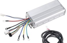
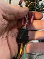
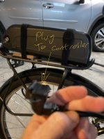
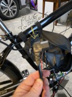
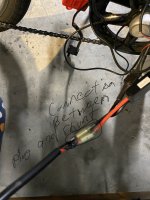
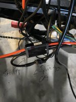
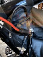
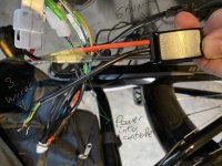
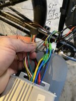
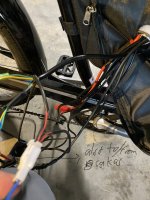
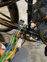
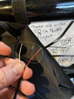
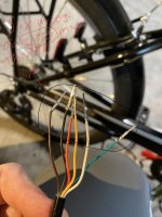
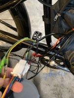
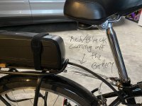
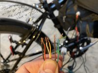
I have a 48v 1000w system with a thumb throttle that has an on/off switch. I bought a CA with a stand alone shunt and a two-wire PAS. I’m trying to wire it all together and the wire colors and diagrams are not quite matching up. I am attaching photos of all the wires. Can someone draw me a schematic showing what I attach to what? Thanks in advance. Each photo is annotated.
 

Attachments

  • 7FF07418-73CD-4F6F-8DF0-966C92C7446D.jpeg
    7FF07418-73CD-4F6F-8DF0-966C92C7446D.jpeg
    160.1 KB · Views: 415
  • 6D119D55-BE93-42F4-A08F-6E7EB694A7A2.jpeg
    6D119D55-BE93-42F4-A08F-6E7EB694A7A2.jpeg
    139 KB · Views: 415
  • CF9AD15A-F95E-433B-A9D8-9DC19896248A.jpeg
    CF9AD15A-F95E-433B-A9D8-9DC19896248A.jpeg
    176.8 KB · Views: 415
  • A17745C6-B42B-415B-80A2-8B291909E31F.jpeg
    A17745C6-B42B-415B-80A2-8B291909E31F.jpeg
    202.3 KB · Views: 415
  • 6EF92F03-B915-4CC3-B3F4-DEE49EEA59A0.jpeg
    6EF92F03-B915-4CC3-B3F4-DEE49EEA59A0.jpeg
    169.9 KB · Views: 415
  • D2A4C6DC-0D4A-4A92-9EBD-C0C8DDC88CA6.jpeg
    D2A4C6DC-0D4A-4A92-9EBD-C0C8DDC88CA6.jpeg
    187.1 KB · Views: 415
  • 9B100B48-51C1-4117-A563-2B2CBD3293E2.jpeg
    9B100B48-51C1-4117-A563-2B2CBD3293E2.jpeg
    317.8 KB · Views: 415
  • 30B6C165-A61F-4A77-B17A-DB6133C5D322.jpeg
    30B6C165-A61F-4A77-B17A-DB6133C5D322.jpeg
    208.9 KB · Views: 415
  • B4A9F113-3F37-4ADF-B410-E727CE2B5CB3.jpeg
    B4A9F113-3F37-4ADF-B410-E727CE2B5CB3.jpeg
    267.1 KB · Views: 415
  • 653118E9-A341-4B0C-B9E8-24CBB5D6632D.jpeg
    653118E9-A341-4B0C-B9E8-24CBB5D6632D.jpeg
    225 KB · Views: 415
  • 05A5E5DF-CCC3-449B-B90A-EB5C8567D75D.jpeg
    05A5E5DF-CCC3-449B-B90A-EB5C8567D75D.jpeg
    150 KB · Views: 415
  • 2C7CD6AD-CC9D-4AFC-8813-7F30B8DE672D.jpeg
    2C7CD6AD-CC9D-4AFC-8813-7F30B8DE672D.jpeg
    192.2 KB · Views: 415
  • 833FC497-D08F-43D4-AAE8-051EB0DF13E2.jpeg
    833FC497-D08F-43D4-AAE8-051EB0DF13E2.jpeg
    162.8 KB · Views: 415
  • 0CE05D90-5E8F-4806-88B3-6FD74FBD0D15.jpeg
    0CE05D90-5E8F-4806-88B3-6FD74FBD0D15.jpeg
    178 KB · Views: 415
  • 1F139504-3225-4849-B3F0-49D86A2CA2D7.jpeg
    1F139504-3225-4849-B3F0-49D86A2CA2D7.jpeg
    239.2 KB · Views: 415
  • 68EF5A8B-585E-4C58-A107-3EF1E48E51CD.jpeg
    68EF5A8B-585E-4C58-A107-3EF1E48E51CD.jpeg
    364.2 KB · Views: 415
  • A6514D27-C6CC-481C-AD16-B8BEBE5B90B1.jpeg
    A6514D27-C6CC-481C-AD16-B8BEBE5B90B1.jpeg
    278.9 KB · Views: 415
Lets do a quick bump and warn that the rear rack may break with the battery on the rear rack.
Vibration alone will undo the bolts if you havent added blue thread locktite.
Then if your real careful and always have your bike upright, and your bike never falls... you may be alright.

...and so its time to add some quality to my post.

That is a typical problem as the human robots on slave labor wage will grab any color wire nearest to them, or easiest to get. But you can be guarunteed that the quality control on the Cycle Analyst won't have the same problem of random colored wires. Besides that there is no standard, and if there was a standard some, maybe most won't follow the standard. Pics of full bike would be alright to. :thumb:
I’m trying to wire it all together and the wire colors and diagrams are not quite matching up.


OK so lets get this absolutely straight. You have a Cycle Analyst, what version?
Where did you buy your controller from and what exactly is it?
Are you using Pedal Assist, generic or torque sensing?
Out of curiosity, what motor you running, what voltage, what ah, what discharge rate, where did you buy your battery from. Full shot pics of the ebike would be good to :thumb:
Can someone draw me a schematic showing what I attach to what?
 
The CA is version 3. I bought it from Grin. The ebike upgrade kit is a generic 1000W 48v I bought from Wish. The battery is one I bought off Amazon. I rode it without the CA as a throttle only many times — the rack is solid!
 
sfshoyajon said:
Correction — CA 3!
A few questions:

  • Does the controller have a Cycle Analyst direct plugin connector?
  • Do you have a link to the kit/controller?
  • Is the PAS sensor from Grin?
 
I tried a direct plug from the CA to the controller. The plug into the controller is a 6-pin, so in theory it should be direct. But the wire out from the throttle is also a 6-pin. No power went through the system when I tried that,
 
Like the Yescom kit in this picture
 

Attachments

  • 97E2921E-4DD7-4E11-88AC-23581B2E601F.jpeg
    97E2921E-4DD7-4E11-88AC-23581B2E601F.jpeg
    186.9 KB · Views: 354
  • F07D2D31-D3A6-402C-BC97-02AA29E76D68.jpeg
    F07D2D31-D3A6-402C-BC97-02AA29E76D68.jpeg
    54.1 KB · Views: 354
sfshoyajon said:
I tried a direct plug from the CA to the controller. The plug into the controller is a 6-pin, so in theory it should be direct. But the wire out from the throttle is also a 6-pin. No power went through the system when I tried that,

Unless the controller specified a CA direct plug, it likely doesn't have one. Since you have the SA model with external shunt module, the basic connections will be the PAS, throttle, and brake level switches connect directly to the CA. The CA direct plug goes to the external shunt module. The green wire coming out of the external shunt module is the throttle signal wire, that would connect to the signal wire of the connector where you originally connected your throttle to the controller.

Can you post a pic of the connector on the controller where the throttle originally plugged in? Assuming that you used the button on your throttle to power the controller on and off, you may need to separate out the throttle signal wire from the connectors, both on the controller and throttle connectors.
 
Here it is. I already separated out the wires. Thanks for taking a look.
 

Attachments

  • 1E56D90C-43D6-4930-A46D-9A1B0DCD3A54.jpeg
    1E56D90C-43D6-4930-A46D-9A1B0DCD3A54.jpeg
    150 KB · Views: 350
sfshoyajon said:
Here it is. I already separated out the wires. Thanks for taking a look.

I think the only wire that needs to be separated out from the 6 pin connector from your original throttle, is the throttle signal wire, from both the controller side and throttle side connector. Basically, both the PAS and throttle signals that go to the CA are converted to a a throttle signal that goes to the controller. Probably should first get the throttle working, via the CA, and once that works, connect the PAS to the CA. From there it's just adjusting the settings of the CA.
The brake cutoff switches could go directly to the CA, so the only cables running back will be the CA cable, PAS, and speedo.
 
If the throttle outs are
Red cable : +5V
Blue cable : - negative
White cable : signal
Green cable : battery voltage indicator
Yellow cable : + positive of switch
Brown cable : - negative of switch

And the throttle inputs for the CA are
5v Red
GND Black
Thi Green

Does the white wire from the throttle connect to the green?
What wires connect to throttle in?
 
sfshoyajon said:
If the throttle outs are
Red cable : +5V
Blue cable : - negative
White cable : signal
Green cable : battery voltage indicator
Yellow cable : + positive of switch
Brown cable : - negative of switch

And the throttle inputs for the CA are
5v Red
GND Black
Thi Green

Does the white wire from the throttle connect to the green?
What wires connect to throttle in?
Problem is that you don't have a throttle; you have several buttons. I would replace them with a real throttle. If you want to keep the buttons, then you can:

1) wire them up as an aux switch to the CA (does the 2.3 accept an aux switch on its aux input? not sure) and use it to control boost level (you can also add a throttle alongside this)

2) do a voltage divider so that one button gives you half power and the other gives you full power (use torque throttle mode.)
 
https://endless-sphere.com/forums/download/file.php?id=303902

I have a thumb throttle with an on/off switch integrated into it.
 
If the white wire is your signal wire from your throttle then it would connect to CA green input. Follow E-HP guidance. If you have questions ask. You all most have it.

by sfshoyajon » Oct 18 2021 9:45pm

If the throttle outs are
Red cable : +5V
Blue cable : - negative
White cable : signal
Green cable : battery voltage indicator
Yellow cable : + positive of switch
Brown cable : - negative of switch

And the throttle inputs for the CA are
5v Red
GND Black
Thi Green

Does the white wire from the throttle connect to the green?
What wires connect to throttle in?
 
Back
Top