Hi Guys,
I recently purchased a used non-working converted electric mountain bike, and I am in the process of making it working.
The issue I am facing right now is how to connect the brake cut off connectors.
The electric cables from the bike's two brake levers were cut when I purchased the bike, so I don't have the end connectors. On the controller side, it has a 3-pin male brake cut off connector.
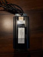
The controller is a Crystalyte 36-48V35A. Each of my brake levers just contains a on-off switch with two wires.
I wonder what is this 3-pin brake cut off connector's pinout?
Once I figured out the pinout, I can fabricate some type of connectors and make them work.
Thanks!
HH


