
bj97301
100 mW
- Joined
- Mar 19, 2020
- Messages
- 39
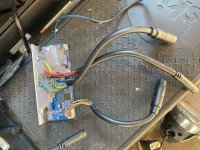
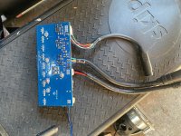
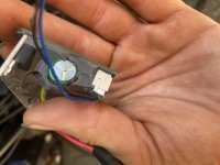
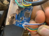
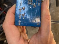
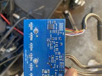
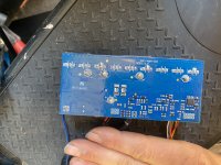
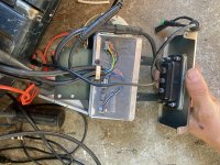
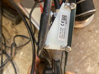
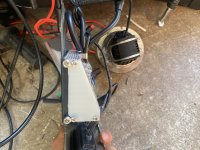
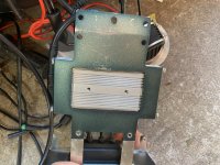
A customer purchased a truckload of these skip scooters(called skip aka Hellbiz to verify purchase already). We are hoping to get em back on the road without replacing the controllers. Has anyone seen this before? Can you point me in the right direction with regards to what wires need to be connected to get the controller to turn on? Otherwise, I’ll be doing brute force and it’ll be a controller massacre. 
Power to the controller is solved(big red and black wires). The next step is to turn it on. Usually controllers take battery positive and run it to a switch then back to the controller to turn it on. I need to find the wire to potentially run the bat pos back to so that it will turn on the controller.
The old components used a remote turn on mechanism. I was not able to get the scooter to turn on that way without the remote api.
Attachments
-
 1A0B38EB-3F44-479C-828B-BBC41E324F93.jpeg3.8 MB · Views: 290
 -
 AFF06504-BE2B-4385-ACBA-74B03AB3AC93.jpeg3.7 MB · Views: 290
 -
 886FF3C0-6814-4C1A-AC91-D0B463C814AD.jpeg2.9 MB · Views: 290
 -
 219A7E84-CAA3-43CC-AEE5-A3EC81D546D9.jpeg2.8 MB · Views: 290
 -
 0CB85D07-B197-46FD-976A-5F9ADDAD3F17.jpeg2.8 MB · Views: 290
 -
 F083856E-90F7-446B-964B-AA917067A2B4.jpeg2.9 MB · Views: 290
 -
 7686E726-D43C-4DF2-B49A-E7865C3D15C8.jpeg3.1 MB · Views: 290
 -
 22A4DBAF-DF70-4291-B6E9-C8C39A3DD11C.jpeg3.6 MB · Views: 290
 -
 17D20795-0DD8-4891-A2A6-B4850CD6C141.jpeg2.9 MB · Views: 290
 -
 D3F52DD9-12D6-40AC-903B-B3F937CCAA93.jpeg3 MB · Views: 290
 -
 2020BD26-2797-4C43-B838-3E30AA49DCFA.jpeg4 MB · Views: 290
")

 .
.  . Will hopefully last many years and keep it out of the landfill for at least a bit.
  . I’ll be sure to post an update soon. Shipment is running late.