rkosiorek
100 kW
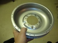
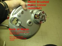
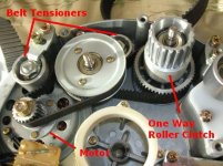
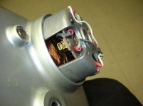
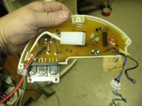
this motor is a PAS only 250W hubmotor with everything built into the hub except for the batteries. built into the hub are the motor, controller and torque sensor. two wires connect to the outside world one pair goes to the 24V battery pack and a small gauge set of wires go to a handle bar mounted ON/OFF switch.
this motor was removed from a Mikkado Volta bike. the owner was tired of the PAS and wanted to convert it to a POD throttle operated motor.
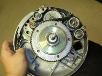
so the first thing i needed to do is gut the motor and take some pictures.
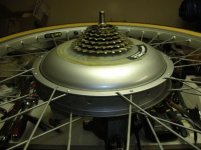
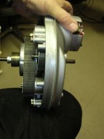
spokes on this thing were really beefy 12Gage spokes like those used on Sulky wheels used in harness racing
this motor was removed from a Mikkado Volta bike. the owner was tired of the PAS and wanted to convert it to a POD throttle operated motor.
so the first thing i needed to do is gut the motor and take some pictures.
spokes on this thing were really beefy 12Gage spokes like those used on Sulky wheels used in harness racing