Raged
1 kW
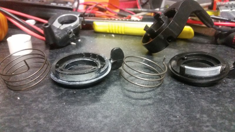
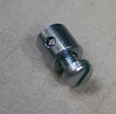
I'm building a cable operated linear throttle for my new build where I will use the front deraileur adjustment on a STI (dropbar) arrangement on a custom 29er setup.
Am I right in thinking this is pretty much how a hall sensor throttle can be set up?
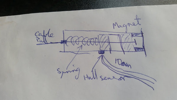
Is there anything more complicated I'm not taking into account?
Am I right in thinking this is pretty much how a hall sensor throttle can be set up?
Is there anything more complicated I'm not taking into account?

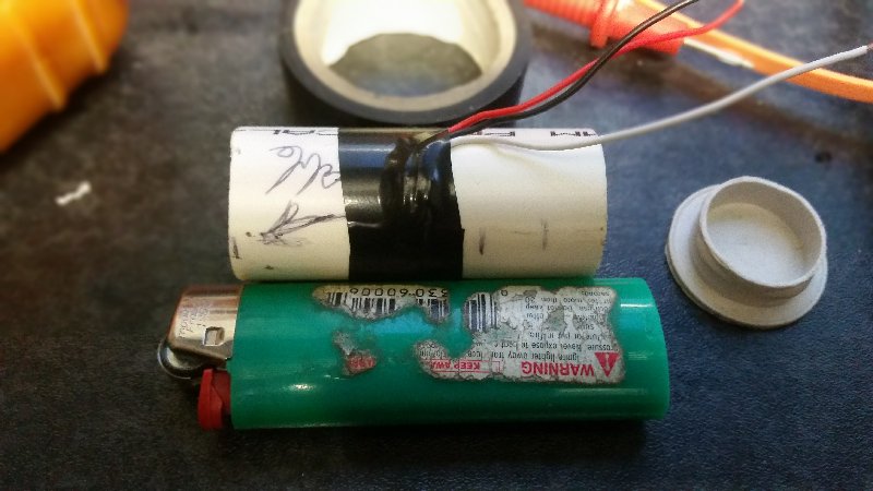
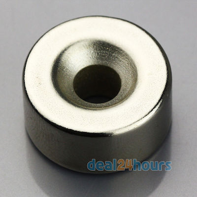

 ... it is fine for short pull cables but if you want to use a MC throttle for example you need around 3-3.5cm of throw/pull plus the gap for the spring which will need to be around another 3-3.5cm, then add around another 1-2cm for cable fixing and end caps so you end up with quite a longish tube.. remember to use a SS spring as a steel spring will upset the range of throw also as will the cable nipple at the end of the cable unless its SS or ali. i have been re-thinking about my attempt of making a tube type sensor and attempting to make it shorter than my first attempts by running the spring down the middle of the magnet so you dont have the compressed spring taking up approx 1-1.5cm in the empty space in the tube at full throttle.