Long story short - I originally built my bike with 12V motorcycle-style headlight/taillight/turn signals and last summer added a brake light controlled by the normal 5V ebrake signal to the controller. This last addition was to become a post my build thread, but it seemed that a new thread about wiring a complete generic lighting installation might be more useful. So here we go... 
Some builders don't feel comfortable assembling custom stuff (soldering PCBs, etc) so the idea here is to use cheap available off-the-shelf parts and point-to-point wiring to get lighting features that will work on pretty much any ebike regardless of the controller, ebrake sensors, or light type (LED or incandescent). Total parts cost for all the electronic gadgets used here should be about $15-$20 or about $5 if you just want a basic 12V brake light.
Three different lighting issues are addressed and separate demo circuits show how to implement each:
The Brake Light Problem
Brake lights are not supported by common ebike controllers and present a common obstacle that is often addressed using extra switches (e.g. magnetic reed or chopper brake switches). We are instead interested in using the generic ebrake signal delivered to the controller of any ebike - regardless of how it is generated. Needless to say, if you have no ebrakes, then this approach isn't for you...
An Ebrake Solution
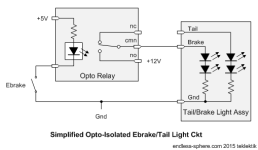
Our approach uses an opto-isolated relay to isolate the low-current 5V side of things from the 12V big-current side. The basic idea might be drawn like this:
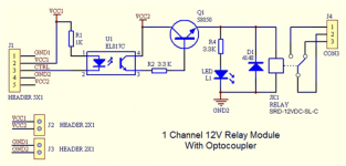
The opto-relay is the critical and seemingly uncommon ebike part, but it's actually a very common microcomputer part! Such things are available as '12V Opto-Coupled Relay Control Boards' and can be had for $3-$4 on eBay. The only slightly tricky part is ensuring that the board has both low-true input and isolated 5V supply pins. Shopping for a combined 'Hi/Lo true' input (or trigger) pretty much ensures that both connections to the resistor and opto-isolator are routed to input pins distinct from the 12V driver back end, although many (most) of the plain 'low-true' types seem to have the proper design as well. I found some suppliers will forward a schematic which answers any questions immediately.
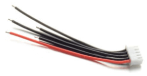
I can recommend this opto-driver board on eBay. It has nice construction, easy connections with clear markings, and a schematic. I used a 4s JST battery balance lead from eBay for the input connections, but soldering is always an option.
Turn Signals
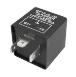
Common automotive flasher relays make turn signals easy to wire. The only matter to keep in mind is that some flashers expect a heavy current draw to work and don't work with LED lighting. The possible benefits of LED vs incandescent turn signals is another discussion, but there is no real difference in wiring, so just get a LED-compatible flasher (they can drive either type) and be done with it. A CF13 JL-02 LED-compatible flasher relay is a good choice for about $5 on eBay. These are often sold with a socket, but standard 1/4in FastOn connectors work fine and may help in tight installations.
Here's the basic turn circuit for simple 3-terminal automotive flashers:
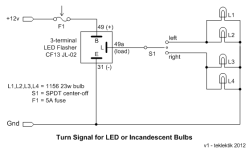
This scheme mates up directly with common motorcycle turn signal switches as well as the familiar controller '3-speed' switches (SPDT center-off). Again, although shown with incandescent bulbs, LED parts work the same.
Brake Lighting and Strobe
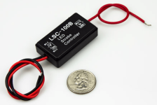
Standard 12V lighting can be strobed using a LSC-100B strobe module available from SuperBrightLeds for about $5. As the picture shows, this is a tiny thing and easy to hide. Wiring is equally easy.
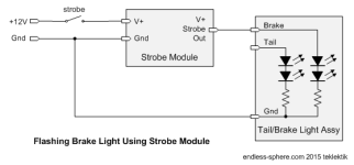
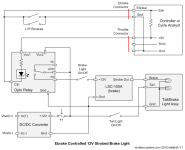
This strobe module can be combined with the ebrake circuit above to normally strobe the brake light and turn it on continuously when brakes are applied - just hook up the sample strobe circuit above to the normally closed relay contact. This addition might look like this:
View attachment 13
EDIT - For folks not too comfortable with the wiring instructions above, here's a pictorial wiring diagram from a subsequent post in the thread that shows the bare minimum ebrake/strobe hookup without switches, etc. For only a basic brake light w/o strobe, just leave out the black LSC-100B strobe module and its three connections.
(Be sure to check pin labeling in case the board layout differs from as shown...)
View attachment 1
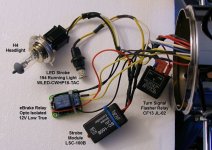
The wiring for this is simple point-to-point stuff and there are no special considerations for length of wire runs, etc - you can position the parts up front, midway with the controller, or wherever it's convenient. Any lighting can share the same ground wires wherever that simplifies wiring. The strobe and flasher relays are automotive parts and pretty physically robust, but the opto-relay board is a computer part and deserves a little attention to avoid shorts to the connectors and traces. I removed the nylon mounting pins, put a square of plastic on the underside (like from a deli container lid), sleeved it with heatshrink, and tucked it away in the headlight housing. The parts would all fit easily in a small project box, an electrical junction box, a short length of 2inch PVC pipe with endcaps, etc. Below you can see the components in my build just loosely wired up. They just get stuffed into the bobber headlight and are completely hidden.
So - that's pretty much it circuit-wise. Just pick and choose the parts or features that seem interesting to your build.
A Special Note About Lighting Grounds
Most if not all contemporary automotive lighting assemblies have a neutral mount and bring out a separate ground wire. However, many of the motorcycle choices instead use a live frame ground for the sake of compatibility. Hooking up a live frame ground to the traction battery is generally considered A Very Bad Plan on an EV and so you may need to either find alternate lighting, run the 12V DC/DC converter isolated (i.e. do not share the 12V ground with the traction battery ground as shown earlier), or simply modify the lighting assemblies.
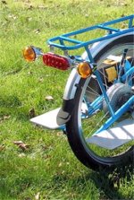
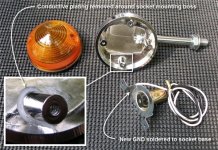
The illustration below shows an example of isolating a lamp socket from the frame and adding a ground wire. In this case the turn signal is plated plastic and the plating carries the frame ground connection. A solution is to use a Dremel tool with a small round burr bit to remove the plating around the socket mounting bosses - thus isolating them, then attach a new ground wire to the lamp socket itself. Lacking a Dremel, you might use a sharp knife to scrape the plating off the sharp edge of the boss face to isolate the round mounting face from the cylindrical boss body. Other lights may use different mounting schemes, but the conversion strategy will be similar.
Anyhow - sort of a long post, but I hope a workable recipe for cooking up motorcycle-style lighting.
A few bucks worth of parts and a bit of wiring should get your lights working in no time.
- In any case - this thread is NOT a discussion of whether or not ebike lighting is A Good Idea from a safety or any other standpoint.
It's expressly about how to get the lighting working for those who want it...
Some builders don't feel comfortable assembling custom stuff (soldering PCBs, etc) so the idea here is to use cheap available off-the-shelf parts and point-to-point wiring to get lighting features that will work on pretty much any ebike regardless of the controller, ebrake sensors, or light type (LED or incandescent). Total parts cost for all the electronic gadgets used here should be about $15-$20 or about $5 if you just want a basic 12V brake light.
Three different lighting issues are addressed and separate demo circuits show how to implement each:
- ebrake-activated brake light,
- turn signals with an optional indicator or beeper, and
- a strobe circuit.
- Note: 'Annoying details' are called out and indented - skip them if you just want to get the big picture...
- Details: Automotive '12V' stuff is not really 12V at all - that's really an industry term for '13.8V-16V' - not an actual operating voltage. So - at the outset we are expecting to find a '12V' source to drive this lighting that may be a '12V' DC/DC converter (usually 13.8V) or perhaps a 120VAC wall-wart supply (e.g. like a Toshiba ADP-60RH laptop supply). Use of switching supplies is not the topic here and is mentioned only in passing to note that lighting will appear noticeably dimmer if actually operated from 12V, whereas a nice 15V or 16V converter will add some visual punch - it's actually 'in spec' for the lighting components.
The Brake Light Problem
Brake lights are not supported by common ebike controllers and present a common obstacle that is often addressed using extra switches (e.g. magnetic reed or chopper brake switches). We are instead interested in using the generic ebrake signal delivered to the controller of any ebike - regardless of how it is generated. Needless to say, if you have no ebrakes, then this approach isn't for you...
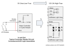
- Details: The illustration below shows the two ends of the problem: a generic controller or CA V3 ebrake connection and two conventional taillight assemblies - one incandescent and one LED. The ebrake system works by having a pull-up resistor internal to the controller that holds the Ebk signal high. When the ebrakes are applied, the Ebk signal is brought to Gnd signalling braking with a 'low-true' signal. The currents through the ebrake switches are tiny (a few ma) and the switching may be provided by mechanical or magnetic switches or electronically via hall sensors (e.g. HWBS - hidden wire brake sensor). The lighting assemblies illustrate what must be driven - these are commonly two lamp brake/taillight units with a common ground that must be driven by switching 12V to either the brake/tail light sections. Common currents per bulb for incandescent systems are around 2A and about 1/4A or less for LED units - your mileage may vary...
An Ebrake Solution
Our approach uses an opto-isolated relay to isolate the low-current 5V side of things from the 12V big-current side. The basic idea might be drawn like this:

- Details: An opto-isolator is basically an LED and photo-diode sealed in a light-tight chip. Turn on the little LED, the photo-diode sees the light and makes a signal that can be amplified to turn on a relay. The relay contacts are hefty, electrically neutral, and can be hooked to whatever we wish.
Here we see two interesting things.- The hookup of the opto-relay front end can be done in a manner that looks very much like the ebrake/controller circuit (better for sharing signals).
- The 12V lighting is switched in a nice isolated way with the exception of the shared ground.
- More Details: The 12V accessory ground and the traction battery ground don't need to be shared, but most common 12V converters use a shared IN-OUT ground, so it's drawn that way here to minimize confusion. Sharing ground isn't an issue until the battery voltage gets really high and complete 12V accessory isolation is a matter of safety. That said, isolation can be a solution to unavoidable 12V frame grounds due to old-style lighting (see below).

- Details: This works by paralleling the controller low-true 5V input with the opto-relay 5V low-true input so that closing the ebrake switch drags both inputs to ground. So - when the ebrake signal goes low (to ground) the controller cuts the motor power and the opto-relay delivers 12V to the brake light. Easy-peasy.
We are borrowing 5V from the throttle connector - wire this up any way that's convenient - it's typically the red throttle wire. If you are using a CA V2.3 or V3, you can pull the 5V from the CA throttle or AuxPot connectors or if a V3 just plug into the unused controller throttle connector. Ebrake connectors typically have a black (GND) and yellow or other color for the Ebk input - the polarity is important to get the opto-relay to operate properly. If the wire coloring is not revealing, test across the two ebrake pins of controller or CA connector with a DMM. If the meter shows about +5V the red meter lead is on the Ebk pin, if it shows -5V the black meter lead is on the Ebk pin.
The opto-relay is the critical and seemingly uncommon ebike part, but it's actually a very common microcomputer part! Such things are available as '12V Opto-Coupled Relay Control Boards' and can be had for $3-$4 on eBay. The only slightly tricky part is ensuring that the board has both low-true input and isolated 5V supply pins. Shopping for a combined 'Hi/Lo true' input (or trigger) pretty much ensures that both connections to the resistor and opto-isolator are routed to input pins distinct from the 12V driver back end, although many (most) of the plain 'low-true' types seem to have the proper design as well. I found some suppliers will forward a schematic which answers any questions immediately.
I can recommend this opto-driver board on eBay. It has nice construction, easy connections with clear markings, and a schematic. I used a 4s JST battery balance lead from eBay for the input connections, but soldering is always an option.
- Details: I have sampled several different boards, some with screw terminals for both input and output and all worked satisfactorily on the bench. This unit just happens to be the one that fit my cramped mounting situation and has lots of miles on it. So - very high tested confidence, but not particularly 'special'. If the LED/resistor front end on a schematic is isolated from the 12V (similar to the one above), you should be good to go. Also, 'combined Hi/Lo trigger' boards often have a little selector jumper you must set properly (to Lo). Some boards may mention 'Arduino', but it's just a particular kind of microprocessor - not important - the 5V interface we need is the same.
Turn Signals
Common automotive flasher relays make turn signals easy to wire. The only matter to keep in mind is that some flashers expect a heavy current draw to work and don't work with LED lighting. The possible benefits of LED vs incandescent turn signals is another discussion, but there is no real difference in wiring, so just get a LED-compatible flasher (they can drive either type) and be done with it. A CF13 JL-02 LED-compatible flasher relay is a good choice for about $5 on eBay. These are often sold with a socket, but standard 1/4in FastOn connectors work fine and may help in tight installations.

Here's the basic turn circuit for simple 3-terminal automotive flashers:

This scheme mates up directly with common motorcycle turn signal switches as well as the familiar controller '3-speed' switches (SPDT center-off). Again, although shown with incandescent bulbs, LED parts work the same.
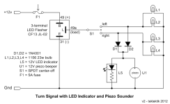
- Details: Unfortunately, motorcycle turn signal switches are non-self-canceling which leads to forgetting to them turn off. One strategy is to add an indicator or beeper to the circuit. This is often done with a 4-terminal flasher, but adding a couple of diodes does the job and allows use of readily available LED 3-terminal units. This is shown below with both alert types in place - just omit either if it doesn't appeal to you.
Brake Lighting and Strobe
Standard 12V lighting can be strobed using a LSC-100B strobe module available from SuperBrightLeds for about $5. As the picture shows, this is a tiny thing and easy to hide. Wiring is equally easy.


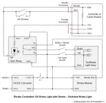
This strobe module can be combined with the ebrake circuit above to normally strobe the brake light and turn it on continuously when brakes are applied - just hook up the sample strobe circuit above to the normally closed relay contact. This addition might look like this:
View attachment 13
EDIT - For folks not too comfortable with the wiring instructions above, here's a pictorial wiring diagram from a subsequent post in the thread that shows the bare minimum ebrake/strobe hookup without switches, etc. For only a basic brake light w/o strobe, just leave out the black LSC-100B strobe module and its three connections.
(Be sure to check pin labeling in case the board layout differs from as shown...)
View attachment 1
- Details:
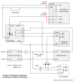
There are a number of options for switching with module locations and number of wire runs being factors. The circuit above shows a way to control the strobe and tail light separately and leave the ebrake function always active. The circuit below shows a variation that allows the ebrake and strobe to be switched OFF for stealthier bike path use and ON for road use. Neither the strobe nor the opto-relay draw appreciable power so they can be wired unswitched to the main power and just the output (light) connections switched if that works out easier in the overall wire harness.
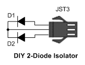
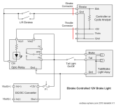
If the headlight system is 12V then that can be tied in to minimize the number of switches. The circuit below is from my build and shows how a couple of diodes can piggy-back the taillight power onto the hi/lo beam switching, eliminating the extra switch. Here you would use the 1A diodes for LED brakes lights and the 3A parts for incandescent. The circuit also shows another variation on switching the ebrake and strobe power.
The bike in this example has a motorcycle light with both an H4 halogen bulb and a small daytime running light in the reflector. Although not shown in the circuit, the running light has been replaced with a socket-compatible LED light and hooked to the strobe output. This gives a front strobe in the headlight unit. The same idea can be used for any secondary light to get a front strobe almost for free (within the strobe power/current rating).
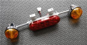
The wiring for this is simple point-to-point stuff and there are no special considerations for length of wire runs, etc - you can position the parts up front, midway with the controller, or wherever it's convenient. Any lighting can share the same ground wires wherever that simplifies wiring. The strobe and flasher relays are automotive parts and pretty physically robust, but the opto-relay board is a computer part and deserves a little attention to avoid shorts to the connectors and traces. I removed the nylon mounting pins, put a square of plastic on the underside (like from a deli container lid), sleeved it with heatshrink, and tucked it away in the headlight housing. The parts would all fit easily in a small project box, an electrical junction box, a short length of 2inch PVC pipe with endcaps, etc. Below you can see the components in my build just loosely wired up. They just get stuffed into the bobber headlight and are completely hidden.

So - that's pretty much it circuit-wise. Just pick and choose the parts or features that seem interesting to your build.
A Special Note About Lighting Grounds
Most if not all contemporary automotive lighting assemblies have a neutral mount and bring out a separate ground wire. However, many of the motorcycle choices instead use a live frame ground for the sake of compatibility. Hooking up a live frame ground to the traction battery is generally considered A Very Bad Plan on an EV and so you may need to either find alternate lighting, run the 12V DC/DC converter isolated (i.e. do not share the 12V ground with the traction battery ground as shown earlier), or simply modify the lighting assemblies.
The illustration below shows an example of isolating a lamp socket from the frame and adding a ground wire. In this case the turn signal is plated plastic and the plating carries the frame ground connection. A solution is to use a Dremel tool with a small round burr bit to remove the plating around the socket mounting bosses - thus isolating them, then attach a new ground wire to the lamp socket itself. Lacking a Dremel, you might use a sharp knife to scrape the plating off the sharp edge of the boss face to isolate the round mounting face from the cylindrical boss body. Other lights may use different mounting schemes, but the conversion strategy will be similar.

Anyhow - sort of a long post, but I hope a workable recipe for cooking up motorcycle-style lighting.
A few bucks worth of parts and a bit of wiring should get your lights working in no time.


