anti-theft signals to controller

Joined
Jul 31, 2012
Messages
61
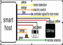
I have controllers that don't have anti-theft plugs and would like to implement them ; what I've found is that, generally, the signals are :
[Red(positive)+ black(power)] on one plug,
[red(e-start) + Blue(motor Lock signal) + Green(Motor Lock)] on the other plug
[edit : can be on same plug, but the same 5 wires always come up with more or less the same description]

what voltage do anti-theft devices use? 48v or 60v (or whatever voltage the battery is), 12v or 5v coming from controller?

I know nothing about where those end up on the controller side ; are there generic pads? How does the motor lock work?

Could it be possible to hack a controller by activating all 3 negative mosfets gates to lock it? Any other ideas (could be with an arduino...)?
 
from http://wholesaler.alibaba.com/product-detail/Ebike-Electric-Bicycle-GPS-GPRS-SMS_60166206808.html

HTB1nCyAGXXXXXXMapXXq6xXFXXXs.jpg


still wondering if those have a standard, but product seems to have a rather standard plug compared to what I've seen on commercially e-scooters ; per it's specs, it seems v+ is taken directly from battery.

this product calls the 3 wires "motor detection" (blue), "electric switch" (orange) and "controller signal for lock motor" (blue)...
 

Attachments

  • HTB1nCyAGXXXXXXMapXXq6xXFXXXs.jpg
    HTB1nCyAGXXXXXXMapXXq6xXFXXXs.jpg
    19.1 KB · Views: 8,237
12fetfinfineonwiring2.jpgfound this image on https://endless-sphere.com/forums/viewtopic.php?f=2&t=8610&start=100

It's from an "infineon" 12fets, looking at the "infineon" eb324-as-2 I have, anti-theft alarms would be wired with v+ and gnd as well as "infineon board" pads identified as Vcc1 (already have the "keyswitch wired to it), Xc and tb...

3 of the wires have been resolved :

v+ to v+, gnd to gnd, "electric switch / e-start / lightning button on remote" goes to vcc1 ; those could easily apply to other controller

read from different sources that tb was motor lock...

could xc be motor detection? I see 4 pads near each other with xc+ and xc-, grouped as dx...
 
checked on a old controller I have, wires were on v+, gnd, ignition, one wire was on the same pad as another wire that I suspect goes to a "sliding charge" led (could be the output to alarm system... maybe a hall sensor signal could do) and the other wire goes to a pad that could lock the wheel...
 
I will work on the infineon in a later time ; right now I need to add alarm features to a controller (the generic one that came with it) on a trike, and I also have a controller that came from greentime.

Looked around and found https://endless-sphere.com/forums/download/file.php?id=90062 ; gives the pads output for a greentime and the trike controller has more or less the same pads nomenclature (the wires already soldered, ie direction switch, speed limit potentiometer, etc., are the same)...
_____________________________
so, wiring the alarm should be wired with :

red to v+ (battery voltage directly)

gnd to gnd

e-start/electric switch to ignition v+ (same as keyswitch)

xc+ (infineon nomenclature) or s+ (greentime nomenclature) to motor detection [I've checked 3 controllers and they all have pads that come in +- pairs, s+ and s- or xc and xc-] ; there's also a2 and a3 pads on greentime, according to leo they are alarm signal and alarm low level signal

tb (infineon nomenclature), a2 or a3 (greentime nomenclature) goes to controler signal for motor lock
____________________________
I'll check with a multimeter, the wires I'm not sure about are motor detection and lock signal, just by turning the wheel and see which of the two outputs a voltage...
 
the greentime I've got has a brown-blue-purple wired plug for anti-theft (anti-theft devices also need voltage from batteries)

brown goes to w pad (a phase), so I assume it's for motor sensing

blue goes to a3 (lock motor)

purple goes to vcc...
 
Hope this info can help.

Orange:
Provides battery positive when the remote on button is pushed and the bike should be turned on. It also provides power when the loud alarm is sounding so that the controller can turn on to apply the brake.

Yellow:
Can be hooked up to any phase wire(big wire) going directly to the motor. When the motor spins it provides a voltage. This is how the alarm knows when to apply the brakes.

Blue:
Is connected to battery negative when the phase wire has a voltage and the loud alarm is sounding.
 
My controllers do not have alarm pads that I can see on the board. I can solder vcc and connect motor detect(to a phase) but I can't see a TB or A2 to lock the motor.
Would it work if I used a small relay and connected the blue from the alarm(motor lock) to pull the relay contacts and short 2 phases together on the controller and ground the brake switch? Or can I ground the phases, would that also work without damaging any of the circuitry?

Ash
 
After some reading and searching I found the A2 pad on the D79F9211 microchip and it's not connected and no way I can solder to it with my setup. I tried connecting to A3 but that didn't lock the motor.
 
My controllers do not have alarm pads that I can see on the board. I can solder vcc and connect motor detect(to a phase) but I can't see a TB or A2 to lock the motor.
Would it work if I used a small relay and connected the blue from the alarm(motor lock) to pull the relay contacts and short 2 phases together on the controller and ground the brake switch? Or can I ground the phases, would that also work without damaging any of the circuitry?

Ash
Bro, after reading your questions, i tried to manage by myself but this time i connected all 3 phase motor using q relay 14 pins and the other 3 pins of relay is (open/not connected), everytime i rotate the motor when the remote key is lock, it alarms and the motor lock but its hard to push, does this damage the circuit?
Because i also read some, they said it is fault line or Short cuircuit?
Thanks in advance ✌️😎👊🇵🇭
 

Attachments

  • IMG20231205133841.jpg
    IMG20231205133841.jpg
    2.3 MB · Views: 3
If you use anything to short motor phases, you need to disconnect hte phases from the controller first.

If you don't, then if hte controller attempts for any reason to place different voltages on any of those phases, it can damage or destroy the FETs in the controller. That could happen simply by turning the controller on at all.
It means it work if i joined 3phase to lock the motor and disconnect the controller?
 
If you use anything to short motor phases, you need to disconnect hte phases from the controller first.

If you don't, then if hte controller attempts for any reason to place different voltages on any of those phases, it can damage or destroy the FETs in the controller. That could happen simply by turning the controller on at all.
Thanks bro, it helps a lot, i already put a relay, everytime the alarm on motor stop, and the power supply to the controller also disconnected, thanks a lot, ✌️😎🇵🇭👊
 
If you use anything to short motor phases, you need to disconnect hte phases from the controller first.

If you don't, then if hte controller attempts for any reason to place different voltages on any of those phases, it can damage or destroy the FETs in the controller. That could happen simply by turning the controller on at all.
I just want to update, i thought its enough to short the 3 phase , and yet it can still be push if someone is trying to still it, how can i totally stop motor to lock it electrically?
Thanks in advance
 
Well, remember that if this is an ebike (not a motorcycle, etc) then it's pretty easy for someone to either just carry it off, or hold the powered wheel offground and walk it wherever they want to (rolling it along on the unpowered wheel). Or toss it into their car or truck and drive off.


Instead of shorting phases, you'd have to have a controller (probably FOC) that can apply a braking force (reverse rotational current) against the rotation. It has to be enough current to completely counter any manual force applied to the bike so the wheel can't move. If the person is persistent enough it could overheat the controller or the motor.

Some controllers have an 'antitheft" that does something like this, but they don't use enough current so you can still move the bike.

It's not just an ebrake we're talking about, either; none of those appear to have the force necessary to hold it at a standstill.

I don't know of a controller that does exactly what you want. If there isn't one, you'd have to create a module (arduino, etc) that when the alarm is activated would monitor motor position via the controller's sensors and if rotation is detected it would apply a throttle signal to the controller to cause phase current to exactly counter that (no more than that or it would go the other direction). Or use one that has opensource code (VESC, Lebowski, etc), and write this into that code.


The catch is, you would have to leave the system functional and powered on the whole time. If they knew enough to bypass the alarm or disable the lock system, it would then be operating normally and they could then just ride away under power. :(
Thanks bro, maybe i will try the reverse thanks 😊
 
Thanks bro, maybe i will try the reverse thanks
I don't know what you mean by that?

If you mean using the reverse setting of a regular controller, that is not what I said at all, and it will not do what you want.

If you use the reverse setting of a regular controller it just causes it to let it spin the wheel backwards instead of forwards.

If you connect that up to your alarm and it engages reverse it does nothing to stop the bike from being pedalled (for a bicycle) or walked away or carried off, even if it would be rather difficult to ride under power. ;)

If your alarm actually engages the motor in reverse it could damage the bike or other things behind it or hurt people behind it (even just passersby or bystanders).

It is also easily defeated by disconnecting those wires.
Thanks for all of your reply, maybe i will do nothing alarm is still the best that i can do, and maybe i will just invest a GPS 🥺 and super big padlock
 
Back
Top