Passion eBike 6 FET Kunteng Controller (S06S)

flangefrog

1 kW
Joined
Jun 26, 2013
Messages
379
Location
Auckland, New Zealand
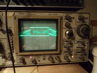
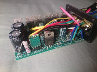
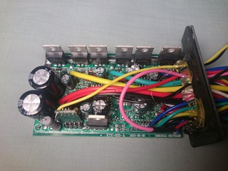
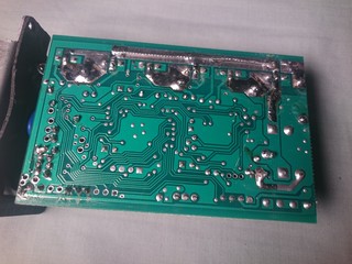
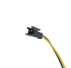
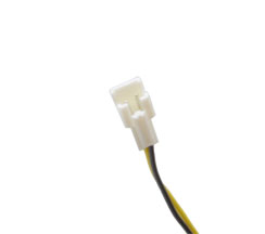
I bought a Kunteng 6 FET controller and S-LCD3 from Passion eBike recently. The controller is supposed to be sine wave, although I haven't confirmed that yet. The controller shown in their picture as of today is a 9 fet version. The size and everything else in the description are correct though except for the phase connections which are female bullet connectors, not ring terminals. The throttle connector pinout here is not how it came, I swapped the black and blue pins.

Controller made by Suzhou KUNTENG Electronics Co., Ltd
Bought from Passion eBike
Direct link to product: Passion Ebike 36V or 48V Universal Silver Brushless DC Sine Wave Controller 250W or 350W Electric Bicycle Controller

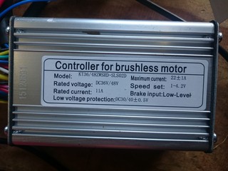
Sticker on the front says the following:
Model: KT36/48ZWSRD-SLS02D
Rated voltage: DC36V/48V
Rated current: 11A
Maximum current: 22±1A
Speed set: 1-4.2V
Brake input: Low-Level
Low voltage protection: DC30/40±0.5V

 
The mosfets are IRFB3306 which are 60V and 3.3mΩ typical. The caps are 63V, 50V (guess that's just what was cheapest) and 16V.

The controller has a lights output so you can control external lights via the LCD. There are two connectors for the lights (see the Aliexpress product description). The one with the white connector gives the full battery voltage but will be disconnected if you remove the pink "ignition switch" loop. The one with the black connector goes to the small daughter board near the LM317T. It has a small fet or transistor on the board. I'll desolder it and have a closer look soon. Here's another thread about adding a light output to an older S06S: http://www.pedelecforum.de/forum/index.php?threads/lichtausgang-am-s06s-controller.26833/

I'm not sure if the controller is actually sine wave or not as I tested it with my Golden Motor BLT-500 (no load, not installed on a bike) and it still buzzed at low RPMs. Any ideas how I can test this without an oscilloscope?

The power connector is an Amass (genuine or fake?) XT60 female and it comes with the matching male connector.

The controller doesn't appear to be a "torque simulation" one. I have seen that the P3 setting may switch it between speed control and torque control modes (is that correct?) so I'll test it again after changing this.

I can't find any good photos of a BMSBattery S06S controller internals. Can anyone take some for a comparison? I'd like to know if it's the same PCB and date.
 
Here is the lights module as promised. The black wire from the black lights connector goes to ground.


The large transistor is a 2SA1013 and the small transistor appears to be a 2SC1815.

This is the schematic. The pins are numbered from left to right looking at the front side with the components.


The circuit is fairly simple. The part I'm not certain about is P1. It seems to be some sort of feedback pin so the micro knows the transistors are working.

These are the connections on the main board:
P1: Microcontroller pin
P2: 5V control
P3: Battery voltage from display connector (only on when controller is enabled)
P4: Ground

When the lights board is installed and the lights are enabled P2 is at 3.35V and P1 is 5.7V (seems high as it's directly connected to the micro).
 
I just tested it out with an 18W (actually measured it to be more like 9W) LED headlamp and promptly let the magic smoke out. I forgot there was a resistor inline with the output and dissipated 2.4W through the 1/4W resistor, frying it (the light worked for a bit!). I think this output is only intended as a switch (the power from the light is supposed to come from the wire with the white connector). I don't see any reason why one shouldn't replace the resistor with a wire. The big transistor is rated at 1A max and most lights take much less than that at the full battery voltage. Edit: just tried tying a wire to both ends of the resistor and it works fine. The light turns on about a half second after the display backlight but turns off at the same time as it.
 
From the aliexpress description, it seems that this connector is for a light switch:

HTB1x7obLpXXXXXqXXXXq6xXFXXXz.jpg


And this one directly powers the light:

HTB1aebULpXXXXaqXFXXq6xXFXXXb.jpg


But is sounds like you've confirmed this on your own.
 
Avitt said:
From the aliexpress description, it seems that this connector is for a light switch:
It's an output that plugs into the light to switch it on and off, it will not accept a switch connected to it. The switch is enabling the backlight on the LCD.

Avitt said:
And this one directly powers the light:
Yes, unswitched except for the "ignition" key. It's just a output with the full battery voltage.

Avitt said:
But is sounds like you've confirmed this on your own.
I did guess how they worked as I have a matching light like this but I wanted to know exactly how it worked, how much current it could handle and how it could be modified. All of the information in this thread should also be applicable to the BMSBattery S06S or other Kunteng controllers for people who want to add a lights output.
 
fellow said:
This is not the S06S controller. Both versions of the S06S controller has LM317 regulator closer to the left (capacitors).
Yes, not quite the same, I just put S06S in the title to help anybody looking for information about it and doesn't know it's made by Kunteng. The only good photo I've been able to find of an S06S is here: http://www.pedelecforum.de/forum/index.php?threads/lichtausgang-am-s06s-controller.26833/ which shows it does have a lights output. I'm not sure if newer ones are different.
 
fellow said:
Here you go, slightly modified S06S V2 (2004- ):
Nice, I'm thinking of doing the same fet mod (and replacing caps) for 14S. Thanks for the photo, would you be able to take another at a lower angle showing the silkscreen markings? Edit: nevermind, I see the photo is from your bike thread.
 
I've updated my second post with a better picture :D .
ice, I'm thinking of doing the same fet mod (and replacing caps) for 14S

There is already modified 13s (48V) version of the S06S on aliexpress for about 40USD with P&P. For 14S,the modification is the same as for 75V i.e. 100V capacitors, 400V snubblers (red capacitors) and 100V mosfets. You have to play with and probably change the "missing" SMD resistor and add the 3v diode (see the second picture note), otherwise the controller will not work when fully charged and the LVC will activate too early/late. It is wise to add the switching regulator in stead of the LM317 and the 3W resistor, both parts get very hot at high voltage.
 
Your version has 22A peak current limit instead of 14A, not sure if it is sine/vector/FOC or not. It should be very obvious, as the sine controllers are very silent. S06S V1 (before 2014) has the full date inprinted (2012-09-16 for example). Difference is the positioning of the LVC SMD resistor, and in the main capacitor(s). The S06S V2 on the second picture is about two years old, but the latest S06S V2 ordered one month ago is identical.

140218 probably stands for 2014, february, 18:th.
 
Will changing the LVC resistor have any effect on the displayed battery voltage?

I borrowed my grandfather's scope and (after learning how to use it) made some tests. This is the sum of the two mosfet gates for one phase. One of the signals is inverted.


Obviously the controller is square/trap not sine. I now realise that the ZWS in the model name means square wave and SVP means sine wave. I think it was an unintentional mistake by Passion Ebike as the description was mostly copied from another of their products and had a few other mistakes. I'll contact them and ask for a partial refund anyway.
 
I had my S06S from BMSBattery on the scope a while ago. This is the "sine wave" they sell it for:

file.php

file.php


Besides the noise the proportion of the rising an falling edges compared to the block looks the same as yours. It's definitly not a sine wave, but not a straigh block either.
I think Suzhou KUNTENG Electronics calls it a square wave, but it is sold as sine wave by BMSbattery and others.
 

Attachments

  • DSC03103.JPG
    DSC03103.JPG
    104.7 KB · Views: 23,358
That's interesting to see. Where did you hook up the probe to? I got the exact same pattern with the noise but I can't remember how I solved it.

I don't think square wave is ever just a straight block - as far as I know what people often call square wave is almost always trapezoidal commutation.

Do you have a photo of your board showing the markings? Is it the same one as fellow's SO6SV2 photo above?
 
I think the probe was connected to one of the phase wires to the motor. The scope is set to 1 V/div and i guess the 10x divider on the probe is set, so that gives about 24 V peak. It's on a 36 V battery. But I'm not sure, it's too long ago.
My pcb is excactly the same as as fellow's, with the same markings.
Being it a sine wave or not, I am quite happy with it's performace and noise level, it's barely noticeable while riding.
 
I received the new controller quite a while ago. This one is actually sine wave although at very low speeds it starts with square wave. Unfortunately I shorted the gate to ground when testing it and I'm pretty sure I killed the gate driver. It's a little SOT-23 transistor with the marking "Y2". Will any generic replacement work fine or does it need to be matched to the other drivers? The replacement I'm looking at is SS8550.

I'm going to be replacing the LM317T with a switching DC-DC converter. Does anyone know if the 15V rail from the LM317 is used (perhaps for driving the FETs?) or can I just get a 5V converter and run it straight to the output of the 78L05?
 
Have a look at this schematic. It's not the same controller, but I think its very similar.
http://www.avdweb.nl/Article_files/Solarbike/Motor-controller/China-BLDC-motor-controller-36V-250W.pdf
 
I upgraded the controller today. I also did the mod on the lights board so it can directly switch the lights on and off.

The switch mode regulator really should have a protection diode connected antiparallel to the input and output but I don't have one with the correct reverse stand off voltage.

Edit: by connecting the regulator input directly to the left hole the bypass capacitor was not in the circuit. I changed it to the hole on the right of the yellow wire and installed a jumper wire where the big resistor was. I had also mixed up a couple of caps (the 25V and 10V ones) so I switched them.

 
This is the inside of the KT-LCD3 (S-LCD3) HMI. There was a little bit of silicone around the edges to seal it. I will need to upgrade the display for 14S. The protocol has been documented by someone here at ES so it would be fairly easy to write a new program for the display for anyone familiar with the STM8. The Ketnus SHD32E22 LCD driver chip is documented and looks very simple to use.

It would be a cool project to make a new circuit board that worked with the LCD (easy to unsolder) the Ketnus LCD driver (or a similar one), an nRF52832 and a thin lithium pouch cell (think phone battery). The wires that plug into the controller would be replaced with a short USB/Micro-USB lead for charging.

 
Back
Top