How to wire BMS

Joined
Dec 24, 2015
Messages
200
Hi folks

I bought two BMS boards to connect to the two 48v 20Ah batteries I have made for my bike. However, the terminals on the boards to connect to the 48V PSU are a mystery to me. They are labelled C, B and P so I have no idea how to connect it to the 48V positive and negative from the PSU.
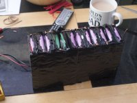
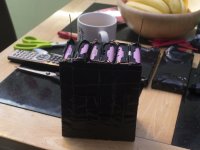
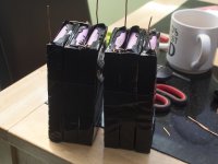
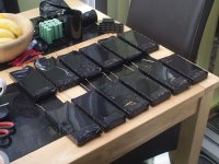
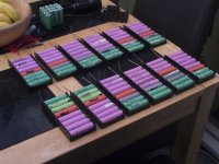
P1180028.jpgView attachment 1P1180026.jpgP1180025.jpgP1180024.jpgP1180023.jpgP1180022.jpg
 
Here I can only see batteries, not BMS...

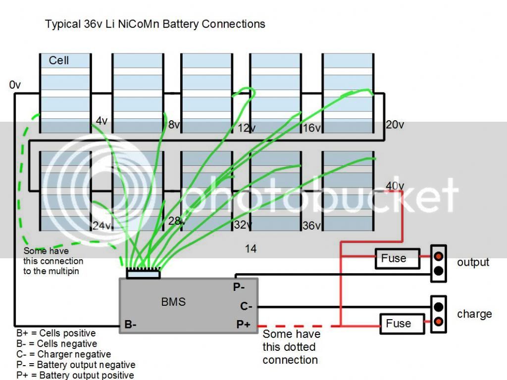
Usually positive side of the battery goes directly to connectors for charger and load.
B should go to negative pole of battery, C to negative pole of charger and P to negative pole of load.
Balancer connector should have one more terminal than number of cells in series.
Most negative balancer contact should have label B0, but it is easily identified as B- terminal of BMS is connected to it internally.

Suggest to post photo of BMS...
 
It's this BMS:

http://www.ebay.co.uk/itm/13S-48V-Li-ion-Lithium-Cell-20A-18650-Battery-Protection-BMS-PCB-Board-Balance-/142002180347?hash=item210ffd50fb:g:8IAAAOSwSWJXQtrO

s-l1600.jpg
 
Does this help? You have to look at the multi-pin connector to see how the cells are connected. The pins are normally marked B0 to B13 or B1 to B13, but if yours is the one in the picture above, B1- is the same as B0, which is ground (0v).

 
Thanks for the diagram. I understand how to wire the balance leads but still not clear how to connect the 48v from the charger to the BMS board.
 
Looking at that diagram and your board the +ve from the charger goes straight to the end battery (+48v) via a fues and not connected to the board?. The board switches the -ve side of the charger to control charge rate.
 
The drawing is confusing, as the charger bit is wrong.

The board gets it's own power via the balance wires. So you can get the balance bit done and the board will be working at that.

Now the board doesn't switch the live wires for the load or the charger. In the drawing, the load(output to controller) is correct. The controller gets it's live straight from the batteries. It's actually it's negative that the bms switches. Allowing the returning neg from the controller to get back to the batteries, Or not.

The charger should be just like the load. The chargers live goes straight to the batteries, and the chargers neg goes through the bms to the batteries, so the bms can switch it off at the neg, not the pos.

Conventionally it seems a bit odd to be switching the negative not the positives, but then conventional current was an early mistake we perpetuate anyway. Electrons flow from neg to pos.
 
Okay, so let me see if I understood:

Connect the 48v positive from the charger to the positive end of the battery

Connect the negative from the charger to the P- connector on the BMS board

Connect the B- on the BMS board to the negative end of the battery

and of course connect the balance wires appropriately
 
Connect Charger -ve to C-.

Connect battery cell -ve to B-.

Connect the -ve output to the motor system through P-.

Most electronic operate switched -ve and has been said current flows from -ve to +ve..
 
friendly1uk said:
The drawing is confusing, as the charger bit is wrong.

The board gets it's own power via the balance wires. So you can get the balance bit done and the board will be working at that.
The drawing is correct. What do you think is wrong with it?
 
d8veh said:
friendly1uk said:
The drawing is confusing, as the charger bit is wrong.

The board gets it's own power via the balance wires. So you can get the balance bit done and the board will be working at that.
The drawing is correct. What do you think is wrong with it?

That isn't his bms. He doesn't have a P+ terminal. We know the dotted lines existence is based on the terminals existence, but the drawing isn't clear about this. The chap is trying to pin down exactly what to do, so an answer of maybe this or that isn't what he wanted. If you edited that part of the drawing out, then it would be right for him.
 
friendly1uk said:
d8veh said:
friendly1uk said:
The drawing is confusing, as the charger bit is wrong.

The board gets it's own power via the balance wires. So you can get the balance bit done and the board will be working at that.
The drawing is correct. What do you think is wrong with it?

That isn't his bms. He doesn't have a P+ terminal. We know the dotted lines existence is based on the terminals existence, but the drawing isn't clear about this. The chap is trying to pin down exactly what to do, so an answer of maybe this or that isn't what he wanted. If you edited that part of the drawing out, then it would be right for him.

The diagram shows a dotted red line with the annotation "some have this connection". I think OP should have enough mental power to figure out whether his BMS does or doesn't have P+ marked on it. Sometimes it's a small pad away from the main ones.
 
I think I've got it now. I'll post some pics of how I've wired it up before I switch it on, just to make sure.

Thanks for all the help guys, much appreciated.
 
keithmac said:
Connect Charger -ve to C-.

Connect battery cell -ve to B-.

Connect the -ve output to the motor system through P-.

Most electronic operate switched -ve and has been said current flows from -ve to +ve..

The charger minus side can be connected to P- too. It is good to know if you want to use only one connector for connecting load or charger.
 
d8veh said:
The diagram shows a dotted red line with the annotation "some have this connection". I think OP should have enough mental power to figure out whether his BMS does or doesn't have P+ marked on it. Sometimes it's a small pad away from the main ones.
Some do yes, so if he has a P+, does his? Some do, some don't, is that what it's saying?
I don't expect any level of understanding from somebody asking questions about a 3 wire issue, and certainly wouldn't add a 4th into the mix that isn't even there. It's not helpful. So I guided him away from it. In order to cast it from his mind and get a clean sheet start.


Peter.bp How would it charge after an lvc event, when the output fets are open. Then during charge, how would the board protect from a hvc event.


This thread is getting a bit too thought provoking. The OP just needs to know about his 3 wires.
 
Peter.bp said:
keithmac said:
The charger minus side can be connected to P- too. It is good to know if you want to use only one connector for connecting load or charger.
Some BMSs do not have a charge control MOSFET, so they use the discharge one to control the charge as well as the discharge. That means that the MOSFET switches off at LVC and HVC, but if you have a BMS with a separate charge MOSFET, like OP's, you can't connect the charge negative to the P- because there won't be a high voltage control to switch it off when the battery is fully charged.
 
:oops:
Guy, thank you for correcting me.

I was looking to wrong BMS (which has different labels: P-, Out- and B-) when was writing the post.
Found other BMS with same labels as in this topic, the charger must not be connected to P-, as you said.
 
d8veh said:
Peter.bp said:
keithmac said:
The charger minus side can be connected to P- too. It is good to know if you want to use only one connector for connecting load or charger.
Some BMSs do not have a charge control MOSFET, so they use the discharge one to control the charge as well as the discharge. That means that the MOSFET switches off at LVC and HVC, but if you have a BMS with a separate charge MOSFET, like OP's, you can't connect the charge negative to the P- because there won't be a high voltage control to switch it off when the battery is fully charged.

Just for clarity, that wasn't my my writing in the quote ;).
 
I still haven't wired the BMS up as my soldering iron burned out and I'm awaiting the postman bringing a new one.

As soon as it's done, I'll post pics and you guys can check it's correct before I plug it in and apply electricity. :)
 
Well, I got the new soldering iron and wired up both BMS to both batteries, then tried charging the first one. The damn 48v 7.5A PSU I was using emitted a loud bang and the dreaded blue smoke of death.

So now I'm awaiting the slow boat from China bringing a replacement.

Oh well, everything else on this ebike build has gone wrong, so par for the course!

In the meantime, I've jury-rigged my imax B6 charger to charge up the batteries 6 cells at a time...
 
Are you sure that you wired the positive and negative the correct way round, Don't go by the colour of the wires, Always use a meter.
 
There's no way to get it wrong with this PSU. I suspected it was out of whack because the meter read the output as 43.2v instead of 48v + 5% (I turned the pot up to max).

Now I know why it wasn't charging - 43.2v is below the threshold for the BMS most likely as 12 x 3.7v = 44.4v
 
Back
Top