Cycle Analyst with 2 shunt with new firmware

Joined
Sep 9, 2017
Messages
40
I would really appreciate any help with my problem with Cycle Analyst (CA) V3 CA-DPS and shunts.

I have a solar eBike. I have two motor with each their own controller and throttle.

I have bought two Shunt
1- The standard one - http://www.ebikes.ca/shunt-ca3.html
will be used to measure Consumption
The standard one comme with a 6 pin JST-SM to plug in directly in the CA and on the other side there is
Pass-Thru of Throttle (green) and Speedo(yellow) Wires under Shrink Wrap.

2- The solar-sense shunt - http://www.ebikes.ca/solar-current-sense.html
will be used to measure Electrical production from the solar panel
(16A Hall Effect Current Sensor for Solar CA Firmware)
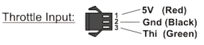
The solar sense came with a 3 pin JST-SM connector, like the Throttle cable.


For now, I would like to keep both throttle and controller separated.

I draw a basic schematic representation of what it will look like once is it over except for the Banfang part.

I am trying to connect the whole things.

Thank you

p.s. my current setup is working, I have two WattMeter but with the new firmware on the Cycle Analyst I can connect 2 shunt so I want to remove those 2 Wattmeter
 

Attachments

  • 2018-08-09 Amalia - Solar + Motor V4 pour quesiton on enelv e stock PDF 100% 72 DPI.pdf
    447.8 KB · Views: 55
To connect the shunts to use the CA Solar firmware CA3.1x19:
  • Connect "P" to the CA3 Aux input connector
  • Connect "C" to the CA3 CA-DP connector

To use separate throttles -- eZee controlled by CA and the Bafang direct:
  • connect the throttle for the eZee directly to the CA throttle input
  • connect the "C" shunt green breakout wire to the eZee controller throttle input, do not connect the breakout black or yellow wires
  • do not use the eZee controller CA-DP connector
  • configure the CA for ThrI->Pass-Thru
  • connect your second throttle to the Bafang directly

Use the wheel pickup that came with the CA-DPS


SolarShunt1-CA+controllers2.png


The standard CA displays will show the Amps/Ah/Wh/etc consumed by both motors and the special Solar displays will show the solar Amps/Ah/Wh/etc for the panels.

Since the CA is reading current from both motors but controlling only one:
  1. any current or power limiting features will not be usable e.g. Current or Power Throttle modes, PAS Basic(Pwr) or Torque(PWR) modes
  2. any ThO controlling feature will affect only the eZee motor e.g. Speed limiting, Low voltage cutoff, thermal limiting, Basic(ThO) PAS. Although current and power limiting will be active, since they must be configured for the max used by both motors, those particular features are not helpful in this configuration
 
WOW !!!
Very precise and to the point
And Very fast !!!

Thank you Very very much.

I was afraid that there were no too many people aware of the new shunt.

I do have more questions :)

A
The throttle input on the Cycle Analyst has 3 wires (taken from the manual.
Position 1 Red: 5 Volts
Position 2 Black: Ground
Position 3 Green: Tni ?

When I take the green wire from the Solar sense, on which position of the female JST-SM do I connect it ? Do I connect only this wire ?


B
Which Setup must I change in Cycle Analyst (CA) ?

C
You mention THO. I looked in CA manual and I found it is Pin 6 of the CA-DPS connector
Is this a Throttle Output ?

D
I do use and really like the option Auto-Cruise Control. With the throttle connected directly to the Ezee controller, I will loose this feature :-(
It might be enough to keep my current setup and not use this solar sense.
It will be a big change for me.

I want to keep both throttle separated because I alternate between motor often, and in big hill, I use both.
I will look into another way to control both motor if I decide to use the solar sense.


Oh I just realize, if your answer for A is position 3, I guess I can still use the other 2 to connect my throttle :)
 
SunPoweredWorldTour said:
A
The throttle input on the Cycle Analyst has 3 wires (taken from the manual.
Position 1 Red: 5 Volts
Position 2 Black: Ground
Position 3 Green: Tni ?

When I take the green wire from the Solar sense, on which position of the female JST-SM do I connect it ? Do I connect only this wire ?
No. the eZee throttle goes to the CA.
I have edited the a-e sections above for clarity - see if the revision helps.


SunPoweredWorldTour said:
B
Which Setup must I change in Cycle Analyst (CA) ?
See the help file in Setup Utility. It describes the settings for the new Solar category.


SunPoweredWorldTour said:
C
You mention THO. I looked in CA manual and I found it is Pin 6 of the CA-DPS connector
Is this a Throttle Output ?
Again, see the help file. The CA implements all control by messing with ThO (CA Throttle OUT - the green breakout wire) - but - there are different modes such as Current Throttle, Power Throttle and a couple of PAS modes that use the shunt-measured current in a feedback loop. Since in this case the CA is also measuring current used by the Bafang and has no idea what you are doing with the Bafang throttle, none of these feedback modes can work. You must only use PassThru Throttle and only PAS modes that do not work by sensing current. Power and current limiting will not work for the same reason and those max limits should be left at the defaults or the max for BOTH controllers combined. Everything else will work normally for the eZee, LVC, autocruise, speed limiting, etc. When you have two identical motors with a single throttle, all CA features work normally since the motors are carrying the load 50/50 - but you have a mixed drive system and so certain features cannot be used because of the unknown current apportionment.


SunPoweredWorldTour said:
D
I do use and really like the option Auto-Cruise Control. With the throttle connected directly to the Ezee controller, I will loose this feature :-(
No you won't. It will still work, but only for the eZee.


SunPoweredWorldTour said:
I want to keep both throttle separated because I alternate between motor often, and in big hill, I use both.
I will look into another way to control both motor if I decide to use the solar sense.
If you wire things as outlined above, one throttle will control the the CA which will control the eZee and the other throttle will control the Bafang. Sharing a single throttle between two radically different drive systems is difficult. This would be trivial if you had two eZees, but you don't, so you are probably going to be stuck with two throttles.

Also - you will need to hook up ebrakes if you use Autocruise. You can either wire one brake lever to the CA and the other to the Bafang, or wire them together and hook them according to Case 2 of the Ebrakes section in the Unofficial User Guide. There you hook the extra wire to the Bafang. This will make either brake kill both controllers.
 
Thank you again

I think I am getting there :)

so in the Consumption Shunt, I take the green wire and put it in position 1 of a female JST-SM and I dont connect any cable to the two other position. Then I connect this to the Throttle input of the Ezee controller.

Time to go to work !

Thank you so much

p.s. I though I would received an email alert when someone answer
 

Attachments

  • Throttle Input Cycle Analyst - Clear.png
    Throttle Input Cycle Analyst - Clear.png
    21.7 KB · Views: 2,486
SunPoweredWorldTour said:
... I take the green wire and put it in position 1 of a female JST-SM and I dont connect any cable to the two other position. Then I connect this to the Throttle input of the Ezee controller.
No.
Green wire to pin 3 (ThI).
 
with the new firmware and the changes to proportional regen I am wondering how to word the question to controller people if their controller (which has a CA JST 6pin connection) will support the proportional regen using ebrake + throttle where as you depress the throttle the brake out voltage will decrease down to 0.0V to give maximum regen? I'm not even sure if I am asking you this right lol

Will your controller support the Grin Cycle Analyst 3.1p15 feature of proportional regen by ebrake + throttle as you depress the throttle the brake out voltage will decrease down to 0.0V to give maximum regen?
 
Ok that's interesting. This seems like a nice way to do proportional regen and through the CA3 even better. Is there something that can be done on the controllers side for this to work with controllers other than Grin controllers? I know there are HOWtos on how to add the JST 6pin CA connector cable to your average controller. Could this be the same thing perhaps. I have just purchase an used CA3 and I am looking forward to getting it in the mail, updating it to the latest FW and going thought the Manuel. I am looking at controllers that have a CA3 cable as an option, and it those that support proportional regen if they could thorough CA that would be great.

PV has a nice 24F 48-120v 100A/200A BT GPS CAcable for $500USD and it would be nice if it could work with the CA3s proportional regen. The other way I was thinking of doing regen is with a throttle that will go both ways. I don't know if there is such a think? but that would work also. Or even a 2nd throttle on the other side. Would either of those work with AC3 and non-Grin controllers?

Oh and I read somewhere that if the non-Grin controller would support remapping of the throttle on brake to "brake out" to 0.0v that it could work? I don't think if I am wording that correctly or not.

I just noticed this is not the CA support thread but a side question. if I need to move my questions to another thread let me know. I don't want to hyjack anyones thread.
 
SunPoweredWorldTour said:
on the production Shunt, there is 3 wire, the green for Throttle, the Yellow for Speedo and a Black
is the black a Ground ?
should I connect it too ?
I recommend no.
Here's the shunt:


CA-ExtMoldedShuntSchem3_small.png


The CA is already grounded to the controller GND so the CA Throttle OUT signal (green wire) already has a GND reference making the black breakout wire unnecessary.

We can see the black wire is also tied to the controller ground. Without this connection, the controller will draw all motor power through the main power wire as intended. If we connect it, the controller will have another smaller path back to the shunt to draw motor power causing current to flow through the controller circuit board from the throttle GND to shunt in ways not originally planned. While there is no strong reason to believe this will have an adverse effect, it was not what the designer intended or tested and since it gains us nothing, I prefer to leave this Gnd disconnected.

However, this is perhaps a matter of an overabundance of caution on my part and frankly, if you hook it up everything will work fine and you may find that the throttle connector is more robustly attached using two wires instead of just one... :D
 
teklektik said:
I recommend no.

WOW Thank you so much
everything work.

I know that I need to be taken by the hand all the way to the end but i really really appreciate it.
you did a lot of my work for me.


I setup the Shunt Value at 1.00 mOhm for the Consumption from what I could find in the Help file
but the watts measure is still off compare to my old system that I kept to compare.

I stil have one problem (that I can see)
in the main display, at the bottom right, the speed is there but it alternate between speed and XXX.XX
could not find why yet.
 
SunPoweredWorldTour said:
I setup the Shunt Value at 1.00 mOhm for the Consumption from what I could find in the Help file
but the watts measure is still off compare to my old system that I kept to compare.
I don't know about the old system but if you need to set the Solar calibration in the new 'Solar' category. See the Help file in Setup Utility for a description. You should be able to calibrate this exactly to your old system or a DMM.


solarCalibration.png


SunPoweredWorldTour said:
I stil have one problem (that I can see)
in the main display, at the bottom right, the speed is there but it alternate between speed and XXX.XX
could not find why yet.
This is because you have no Analogger plugged in to provide GPS data. All the Analogger-related (GPS) data fields blink with (x)'s if there is a comms error (no data) and blink with (-)'s if the GPS satellite data is flagged as unreliable.

Sorry about the general lack of documentation, but this firmware was never really meant to be released (hence the 'x' designation for experimental) - it was throwaway development firmware. I filled in the help file so the settings are described, but the other questions about which you had questions didn't get written up - yet. A similar but more polished firmware release will be forthcoming with better doc, but for now you have to wing the details.... :D
 
teklektik said:
Sorry about the general lack of documentation, but this firmware was never really meant to be released (hence the 'x' designation for experimental) - it was throwaway development firmware. I filled in the help file so the settings are described, but the other questions about which you had questions didn't get written up - yet. A similar but more polished firmware release will be forthcoming with better doc, but for now you have to wing the details.... :D
WOW you're the one who program this... Very impressive !!!
Thank you
I can now remove my 2 other displays, and only keep the CA.

Still working on my bluetooth kit and I now received data :)
I'm very happy, about that.
if you have a list of the data being sent through the serial output, I would really appreciate it.
I live on the third floor, so my bike is too far for bluetooth, so i bought another CA and use it to develop, but other than Tension, I get a lot of zero and I dont know what they are :)
Thank you

p.s. how to I subscribe to this thread. I dns get an alert when there is a new post here.
 
SunPoweredWorldTour said:
if you have a list of the data being sent through the serial output, I would really appreciate it.
I live on the third floor, so my bike is too far for bluetooth, so i bought another CA and use it to develop, but other than Tension, I get a lot of zero and I dont know what they are :)

Here you go. This should be accurate, but field formats may vary a bit...
The possible flags you are seeing in your log is the "Solar GPS" firmware column. The 'g' and 'r' flags indicate if the data from the GPGGA and GPRMC GPS records is valid. if these flags ar absent then the last valid value is logged.


Solar_logFormat_20180911.png
 
teklektik said:
Here you go. This should be accurate, but field formats may vary a bit...
The possible flags you are seeing in your log is the "Solar GPS" firmware column. The 'g' and 'r' flags indicate if the data from the GPGGA and GPRMC GPS records is valid. if these flags ar absent then the last valid value is logged.

I was about to tell you that I received only 14 data separated by a \t and with end of line being a \r
but I realize that in the CA I just bought I did not put the Solar Firmware... so my bad :)
 
teklektik said:
Here you go. This should be accurate, but field formats may vary a bit...
...
I just update my firmware to CA3-13v1S
with the solar beta I received 20 data. I read in the eBikes Blog that you removed the GPS data in v1S. great because I don't have a GPS yet :) (oh I could be using iPhone data)

I am building (at least trying) an iPhone app combine with an Arduino board to receive the data in bluetooth. it will look something like this.


currently I receive the data in string. I did not convert yet into number to select the precision I want.
each square can be moved, and I hope to have the option to remove unwanted data.
and there is a lot of bug but I am having fun :)


with the new firmware, I now received 15 Data. my problem is again to know what each data are and I want to display the info in the App

here is the list I had for the beta solar firmware
SolarBeta.png


Where could I get the new info. or can you modify the text below so I can be up to date :)
Title Unit
1 GMT+Time Hr-Min-SS
2 Consomation Ah
3 V. Battery Volts
4 A Battery Amp
5 Speed km/hr
6 Distance km
7 T Motor Celcius
8 RPM RPM
9 Consomation Watts
10 Torques newtonMetre
11 Throttle IN Volts
12 Throttle Out Volts
13 PasCertain Percentage
14 Solar AH
15 Solar Amp
16 Direction Degre
17 Elevation Meter
18 Latitude Degre
19 Longitude Degre
20 Error Error

Thank you

the project will be open source. it is not yet ready for that but I hope to have it ready for summer for my trip.
 
Hello teklektik

my app is progressing even if I am a bad programmer :)

now I received data from cycle Analyst in a Arduino, send it through bluetooth, then I read the data stream and display it in big square on my iPhone.

what I would like to add is to be able to ask the firmware version to Cycle analyst and from that I will be able to adjust the title and unit of each data , and know the number of data I should received. I will be easy for me to add different configuration for different firmware. Then I will need to restart the data flow.

I have not done this part in Arduino (bluefruit Featjer in fact) yet, but I think I found source code that should do it.

I will put the code open source, but it is not presentable yet :) I plan to do a trip this summer and I want to have it ready for then. It is working now but with many possible source of bug and limited functionality. it should not be hard to add a file to save the data but it is not a priority yet.

do you know the command I should send to received the firmware version and the command to restart the data flow.

thank you

Franco
 
Back
Top