Hall sensor problems, i guess

xfrankie

10 mW
Joined
Feb 11, 2019
Messages
33
Location
58001
Hi guys, long-ish time lurker here.
This is my first post, and already I need some help from the more experienced. Also sorry for the wall of text ahead...

Problem: Hall sensor detection in my Sabvoton 72150 / MXUS 3k combo, I guess...

A little background for those interested:
this motor/controller combo was previously powered by a 52v battery with no problems. But I wanted a lot more range on my bike, so I decided to build my own battery. While at it, why not also up the voltage... so I made 72v35Ah thingy. Even before installing the battery, I feared that the power would overheat my motor (Justin's motor simulator confirmed this). So I decided on adding Statorade to my motor and see how things go from there.
Opening one side of the motor (the cable side) I managed to get just enough space to squeeze some sealant between the side plate and the part between the bolts - it barely moved, as if stuck against a bearing. The other side plate (the chain side) went a lot smoother, adding the ferrofluid was no problem. Then it was sealed as well with silicon based engine gasket sealant. After installing the battery, the fun stopped.


When I twisted the throttle the motor just "hiccupped" forwards and the power was cut off. After lifting it off the ground it spun with no problems. Also when the load was minimal (rider dismounted) and with only a light pull on the throttle it seemed to work (up to around 5Amps of current).

Bridging the BMS power-leads did not help, also the battery rutinely powered a 1 kW hair dryer during testing (I think this rules out a faulty BMS).

When I let the Sabvoton software do a Hall test, it always comes out as "fail", regardless of switching phase leads (as suggested by the software manual.
When turning the wheel by hand while connected to the software, I can see the "Hall status(CBA)" changing in a weird sequence. Not a 123456 , but something like 153624 or something simillar. But it changes at least... However, the automatic Hall test seems to always get stuck cycling between positions 1 5 3 , spinning the wheel very very slightly back and forth repeatadly. Again, there was no such issue before.
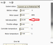
Bez názvu.png

Powering the Hall sensors with 5V , measuring voltage with my multimeter and turning the wheel manually also resulted in changing voltages of the Hall output.
But I read somewhere here that the Hall sensors are "ground referenced" - I assume it means the voltage measured should be between the Output and 0V (ground) wires. But mine were only measurable between Output and +5V (positive). Not sure if this is right or not.

I have no idea what else to do, I really really really dont want to disassemble the motor just to check inside (as if there's something to be seen, ha!). But I will do it when I'm 100% sure the Halls are dead and need replacement.

But if the Halls were damaged by the fluid/sealant, would they register in the software/multimeter?
Is is possible that the Halls are okay and there's something entirely else wrong?

If you could come up with any possible solution, please be so kind and share it with me.
Thanks in advance,
Frankie
 
Sounds like a process of elimination which it seems like you already started.

Don't get so far away from the settings on you controller that you can't get back to stock settings.

Since you are thinking hall sensors, they should read 0v or 5v. (providing your controller is sending 5v to the halls.) The type of hall sensors most ebikes use (usually a Honeywell SS41 or clone.) They respond to alternating poles N or S. as the wheel spins. So when you test them like it says here: https://www.ebikes.ca/documents/HallSensorTestingFinal.pdf you should get a 0v or a 5v reading as you slowly move the wheel.

If those check out, I would carefully check all your connections. Make sure your e-brakes are not engaging and cutting off the motor.

If they look good, charge up your new battery pack, put a proper am meter (either rc style or shunt style) and see if your cells are sagging under load.

Let us know how it goes.

:D :bolt:
 
Hi,
thanks very much for replying!

Just measured the Halls again.

The supply is nice and stable 5.01V

But each Hall output reads 0.02V in one state and only 3.16V in the other - getting this change consistently on all three of them as I "cog" the wheel one way or the other.

Is this normal behavior (due to some resistor in series, like a voltage drop due to resistance?) or is this a sign of dead sensors?

The battery is fully charged (83.6V) with no sag during operation - I do have a wattmeter, and the tests take about 5-8Amps of current, never exceeding what I allowed in the controller.
Contacts of each "Hall color" have less than a millivolt drop across them (proper measuring contact confirmed by also taking a reading against positive and ground, reading 0V and 3.16V respectively).

Resetting the controller to factory setting also had no effect whatsoever.

For the automatic Hall-test I disconnected everything unneeded (brakes, throttle, 3speed switch), but it still was a "fail" as stated by the software.
The controller itself also doesn't report any fault codes, making it seem like it works flawlessly during the tests.

Honestly, I'm stumped... Everything looks like it is working, yet everytime I try to do the Hall test it comes out as a fail...

However, what IS weird, is that before during the auto-tests the wheel got slowly spun around for like a half of a turn. But now it cycles back and forth within a few degrees of angle - about and inch of rolling distance, on a 26inch wheel...

--------------------------------------------------------

Well, scratch all of the above I guess...
Just to be sure, I measured my older no-name motor/controller and there is 4.6V supply and 5.1V output...
So unless 2V drop on the MXUS is considered normal (while the old motor gets a 0.5V boost instead), my best guess is that the sensors really are dead...

Anyone with different experience/opinion, please, let me know.
I'm off to sleep now since its awfully late here, tomorrow I will try to make the Hall auto test on the old motor, just to absolutely rule out the possibility of faulty controller. I will share the results then.

Thanks for your time reading this, and many thanks for steering me in the right direction,
Frankie
 
Hall sensors don't output any voltage, they only short it to ground when on, and the output is floating when off.

A pullup resistor (usually to the 5v source) inside the controller on each signal line brings the output up essentially to the supply voltage.

If you disconnect the halls from the controller and measure the signal lines of the controller, you should get about supply voltage on each one. If you don't, something is wrong inside the controller. (except some controllers use a 12v pullup instead of 5v, but still use 5v to power the halls, so you'd get 12v on each controller signal line).

Measuring the signal lines on teh halsl themselves will get you about 0v regardless of their on or off state, without the pullups connected.
 
Thank you very much for replying, Amberwolf!

(please forgive me is I don't use the correct terminology, english isn't even my 1st language)

I dont know what kind of magic this is, but on the noname controller, the supply is actually lower than the Hall-lines (Hall-phases? colors?). Even though they are supposed to sit behind a resistor?

On the Sabvoton, it was just like before; supply is correct 5V, but all the hall lines are at 3,17V only.

Does this mean that the Sabvoton is damaged? Or am I missing something important here again?

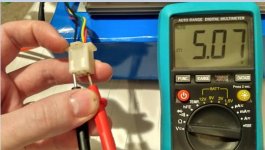
Supply voltage of "no-name" controller:
View attachment 2
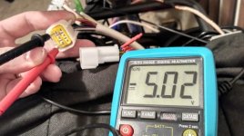
Three hall line voltage measured higher than the supply:
noname 1.jpg
View attachment 4
View attachment 3

Now the Sabvoton was very tricky to measure one-handed and take a photo at the same time, so only one photo of the hall-line voltage. But it was consistent across all three of them:

Sabvoton supply voltage:
sabvoton supply.jpg
Sabvoton hall voltage:
View attachment 1

Could someone with a Sabvoton please help this poor soul out by measuring their Hall connector voltages? Pretty please?

Thanks for your time reading this,
Frankie
 
I know this seems a bit mad but from what I remember I got the self test to work by changing the wheel direction from 0 to 1 or vice versa for the test only. Also set the hall angle to about 140 degs.


Jonno
 
xfrankie said:
When I twisted the throttle the motor just "hiccupped" forwards and the power was cut off. After lifting it off the ground it spun with no problems. Also when the load was minimal (rider dismounted) and with only a light pull on the throttle it seemed to work (up to around 5Amps of current).

If it's only having the problem under load, then maybe you have a loose phase wire connection. The connector may only be making a weak contact and is only working under no/low load?
 
Ok, tell my you are not testing your hall sensors with the connector unplugged. You have the connector plugged in and you are metering through the back of the connector.... Right?

:D :bolt:
 
Hi, thank you all for replying!

@e-beach: I did both. First with the connector plugged. Than Amberwolf pointed out that it should be changing between the full supply voltage (5V) and zero. So then I measured only the controller side, with connector unpluged. And the photos are the result of that.
So now I think that there's something wrong with the Sabvoton itself (as I was seening only 3.1V where there should be 5V), and that the sensors on the motor are ok. Thats why I was asking for someone to measure their own Sabvoton, to see if mine is different or not.
I'm not sure if there's meant to be a 2V drop on the pull-up resistors. And much more confusing to me is the no-name controller, which somehow has higher voltage after the resistors than it has on the supply line.

Also the Sabvoton has the B- (ground) "short-circuited" to its shell -- as measured with my hand when connecting the battery, and then with continuity-check on my multimeter... I'll have to ask the vendor if both of those things are normal or not.
Thanks for the reply, though, sometimes an obvious thing may not be so obvious to others.
-------------------------

@E-HP: loose connections was one of my first thoughts too, no sauce on that though. Everything tight as can be for the ride (which never worked), than everything unnecessary disconnected for testing. Thanks for the suggestion.
-------------------------

@Jonno: thanks for the reply, I'll test that when I get back from work today and report how it went! I definitely got jumbled up during the settings wipe.
 
Jonno said:
I know this seems a bit mad but from what I remember I got the self test to work by changing the wheel direction from 0 to 1 or vice versa for the test only. Also set the hall angle to about 140 degs.
Jonno

@Jonno: tried that today, got the same result as before. The wheel spins about 5 degrees to the left, then about 5 degrees to the right, back and forth... The Hall read-out changes between 1, 3, 5, a few times then the test fails. No other positions from the six seem to engage. They show up when I slowly turn the axle with a wrench, though.
I messaged the seller also, maybe they have some idea of what's going on... We'll see.

Thank you anyway,
Frankie
 
Frankie
I forgot to add turn the "test given amps" up + 5amps or even 7 amps it will work with that combo.
also try 45 and 90 degs.
If it rocks back and forth it will work.

They are pigs to set up so keep trying


Jonno
 
Hi all,
so a few updates on my situation.
Got a reply from the controller vendor today, apparently everything is normal and meant to be this way. I still don't like that the controller shell is "grounded" to B- , but they say it is intentional and so far I had no reason to distrust the QS company. If anything, they have been utmost helpful to me.

Thanks to Jonno I managed to actually complete a Hall test on today's last try.
I tried to complete it using the mobile app and bluetooth, instead of a laptop which I used to test until today.
The "current given" parameter was no issue, as I remembered that it needs to be right around 10amps (from the very first time I put the motor/ESC combo on my bike, maybe a year ago).
What escaped me, however, was the Hall offset, and that for testing it HAS TO BE SET AS 15 Degrees for whatever the hell reason...
Test succesful, new Hall angle detected: 184deg ...
I feel like I won a battle, but not the war.
More updates after I will put the motor back on the bike (tomorrow most likely). Im done for today, take care everybody.

And a HUGE Thank you to Jonno. You may have just saved me from buying a new ESC.

Thank you for reading this,
Frankie
 
Back
Top