My RC Mid Drive with Single Stage Reduction

thepronghorn said:
FZBob, I really like this very simple and clean design. I have been following closely and am thinking about making my own. I also wanted to offer some technical equations for torque and phase amps that could maybe inform some of your motor, current limit, and battery choices.
...

Perhaps you can use some of the above math to help explain why different motors feel different from each other. I would be interested in what you are trying to optimize when you play with VESC current limits as well as what low and high rpm mean when you are reading your watt meter.

Since you have plenty of voltage headroom on your VESC but are butting up against the current limits, lowering Kv will help to move the volts/amps combination away from the current limit.
Thanks for your post. Lots of good information here! I have started to add it into my Excel motor sheet.

My "Low RPM" is about 40, and "High RPM" is around 100-110. I'm estimating, as it has been decades since I've had a cadence meter on a bike, but I'm probably within +/-15%.

I've been setting up the VESC current limits as follows. (Note: I'm not an electric motor expert!) I set the Battery Amps to what is listed on the motor spec. Then I increase the Motor Current Limit (Phase Amps) until I see cogging at low RPM and full load/power, and back off about 5%. I have never seen peak amps on my wattmeter come close to the battery current limit I set, so I don't worry about that parameter. I'm not sure if I'm setting the Motor Current correctly, but it seems to work for me. Since I rarely use over 200-250 watts for more than a few seconds, I may be operating in a very forgiving fashion.

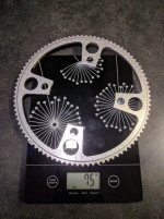
(By the way, just to keep the record straight, I'm using 53 Amp phase current on the orange (D5035) motor.)

So if I was to switch from my 125Kv motor to a 100Kv motor, would you expect a need to change from 4S to 5S ? When I tried a 60Kv motor, it needed 8S...

One thing which has puzzled me for a while. At "Mid RPM", (say about 60 RPM), and even "Low RPM", if I hammer the throttle I see Watts and Amps on my Turnigy wattmeter much higher than expected/predicted. Almost as high as at High RPM, over 400 watts. If Torque is more or less constant over RPM, and I believe it is, I would expect power to be proportional to RPM, and therefore the wattmeter should not show a lot of watts at low and mid rpm. Where is the extra power going? I'm guessing heat?
 
FZBob said:
I set the Battery Amps to what is listed on the motor spec. Then I increase the Motor Current Limit (Phase Amps) until I see cogging at low RPM and full load/power, and back off about 5%.

By the way, just to keep the record straight, I'm using 53 Amp phase current on the orange (D5035) motor.

How could you set the limit so high ? If i set motor amps higher then 30A i get cogging at full load. I tried increasing battery amps but that didn't solve it(lowering it solves it, but then power decreases), the maximum motor current without cogging is 29A. At this level battery amps barely hit 20A, so not more than 300W total.

Here is the phenomenon:
https://youtu.be/Q2mATFNtfxk
 
fixvid said:
How could you set the limit so high ? If i set motor amps higher then 30A i get cogging at full load. I tried increasing battery amps but that didn't solve it(lowering it solves it, but then power decreases), the maximum motor current without cogging is 29A. At this level battery amps barely hit 20A, so not more than 300W total.

Here is the phenomenon:
https://youtu.be/Q2mATFNtfxk

Just watched your video. Mine has always done exactly the same thing on my bike stand. However, since I never use full power at almost stall, it has never been an issue for me in actual riding. In my mind, that's just the motor stalling out.

I determine my motor current by riding up a steep hill in a very low gear, like 22/36, at about 35 to 40 RPM pedaling, and full throttle. I increase motor current until it cogs (less severely than in your video) and back off about 5%. In actual riding I never use full throttle at low RPM, and only rarely at mid or high RPM, when I really have a tough climb, and then I'm working hard too.

Lately I have been occasionally using just a bit of assist from a dead stop when starting in the middle of a steep technical hill, where I would not be able to start without a bit of assist. Not a lot of power, but just enough to help get the pedal moving while I get my other foot up.

By the way, how's your motor mount working out? I'm thinking about doing the same clamping arrangement on my nice bike, as I don't want to drill holes in the frame.
 
FZBob said:
By the way, how's your motor mount working out? I'm thinking about doing the same clamping arrangement on my nice bike, as I don't want to drill holes in the frame.

It's pretty good but it does have some flex to it. The corner sides of the motor plate crack because of the printing/layer orientation but it's still holding up. I will reprint the motor mount with another orientation and that should solve the problem. I could also increase the temperature, because the crack was the result of insufficient layer bonding. This was just the first usable version, i feel it can be improved but i'm lazy nowadays.

I tried to connect the HM10 bluetooth module and i had no luck even though i tried every combination possible. The app sees the bt module but it won't receive any data from VESC. There is one more module 'NRF type' which is used by the mobile VESC tool beside the more expensive metr module. This costs 10usd.
https://flipsky.net/collections/accessories/products/core51822-ble4-0-bluetooth-2-4g-wireless-module-nrf51822-onboard-ws82013
 
Today i reprinted the motor mount in PLA. Took it in my hands and it felt very stiff .. stiffer than ABS for sure.
2irn9yb.jpg


I thought to myself: Nice, i won't have any more problem with chain become slack and climbing on the chainwheel teeth. Guess what ? i was wrong.. and the culprit is (drum-roll pls): the bloody motor shaft. It's flexing like hell when i pinch the chain. So not the printed mounts induce that much slack but the shaft itself. I was thinking that it's a nice hardened steel. Well, 8mm is not enough and it should be supported by bearings on the end. Like your motor cover FZBob which you bought from hobbyking. That should solve the problem.
It should be supported anyway, otherwise i'm very skeptical that the inside bearing will last 1-2 years.
 
fixvid said:
Today i reprinted the motor mount in PLA. Took it in my hands and it felt very stiff .. stiffer than ABS for sure.
2irn9yb.jpg


I thought to myself: Nice, i won't have any more problem with chain become slack and climbing on the chainwheel teeth. Guess what ? i was wrong.. and the culprit is (drum-roll pls): the bloody motor shaft. It's flexing like hell when i pinch the chain. So not the printed mounts induce that much slack but the shaft itself. I was thinking that it's a nice hardened steel. Well, 8mm is not enough and it should be supported by bearings on the end. Like your motor cover FZBob which you bought from hobbyking. That should solve the problem.
It should be supported anyway, otherwise i'm very skeptical that the inside bearing will last 1-2 years.
Is the chain climbing the teeth on the big chainring or the little sprocket? I'm wondering what's causing this because I have never had the issue even when my chain is floppy loose.

I just went out and squeezed my chain, and my motor shaft flexes too. I was actually expecting the bearings to fail from dust, as they are only shielded, not sealed, and I ride very dusty conditions. I will continue to run without the outer bearing support just as a stress test. I got a year and 850 miles on the orange motor before I changed it out last month. When I get some spare time, I will convert my good bike using the old orange motor, and continue testing.

That little sprocket cover with the built in outer support bearing is structurally really helpful. It also looks really nice.

By the way, my motor shaft was definitely soft, as it got tore up when I tried the belt drive and the set screws slipped. I was easily able to file it down. Note that shaft flex (elastic deformation) is not really a function of hardness, as the Modulus of Elasticity is about the same for all steel, hard or soft. Shaft diameter is by far the major factor, as stiffness is proportional to thickness cubed.
 
I made a shaft support with a bearing:

2zz6wcx.jpg


54wpyd.png


It made a big difference in chain slackening. No more shaft flexing. The problem with the chain climbing on the big chainwheel i think it's because my motor is right above the chainwheel and the chain is tangent(vertical) to it. I saw that your motor is mounted more to the front of the bicycle and chain is not vertical like mine. Probably that's why you were trouble free.

My steel chainwheel is also not true because my crank wasn't designed with chainwheels mounted on the exterior. I have to take it to a milling shop to flatten the mounts then buy a nice aluminium chainwheel. Maybe NateTN made some progress with the water jet cut chainwheels.

I found a weakness with the printed motor mounts and it's not flexing but heat disipation. I climbed some smaller hill (and on longer flats) the motor is heated to 65C where i set the VESC to start to cut power. It heats up too easily. The PLA mounts do not disspiate heat and it probably don't help that motor is half enclosed. I need to make an aluminium angle mount, it's just hard to find.
 
So I've started the build on my 12 speed Polygon N8.
Polygon N8.jpg
For this ebike conversion the gearing on FZBob's bike is very good (22T front and 40T back). With the SRAM 12 speed the smallest sprocket is 32T, and a big 50T cassette at the back. Compare the two and FZBob is still better for keeping the motor RPM up during climbing.
His gears meters develop compare to mine.JPG
It was a great suggestion from Briangv99 to use the bash guard ISCG mounts to mount the motor. I started of with the steel 80T sprocket(cheap), just for testing, but ordered the 90T Rebel Gears to keep the price down. She did not ask me again for CNC setup, just $62+ shipping to Australia.
I am concerned about the ground clearance, but will give it a go first. I had to add the round hollow pipe to my bash guard to go from 80T to 90T. Still waiting for the 90T. Bash guard with motor mount.jpg
Bash guard fitted.jpg
I don't have any bag space on the frame. The idea is to build a very flat battery out of 18650 cells, 4S4P, that mounts under my down pipe. Unfortunately all the extra aluminium make it impossible to keep the weight down.
Polygon N8 with motor.jpg
I want to use a push button throttle.
s-l500.jpg
Push the green button, power. maybe 200W. Push the red button in, double the power on the green button (turbo). Maybe cruise control on the right indicator and completely off on the left indicator. This is the idea, with a basic resistor network connected to the ADC input of the VESC controller. Any suggestions on this will be appreciated. Kepler had a great idea with using the Arduino throttle, but I would like to simplify that even more. Not sure if it can be done. Unfortunately, until I finish the battery I cannot run anything. I still have to figure out the controller and the VESC software tool.
Everything is going to be completely sealed, so I ordered the Metr Bluetooth transmitter, so that I can make adjustments later without having to open the box every time.
Any suggestion will be appreciated.
 
fixvid said:
I made a shaft support with a bearing:

I climbed some smaller hill (and on longer flats) the motor is heated to 65C where i set the VESC to start to cut power. It heats up too easily.

Nice support. Do you notice any difference in chain noise? My aluminum support increased noise a bit, especially in the harsh sounding higher frequencies. I suspect it might have been "ringing" a bit...

Just curious - do you know how many battery amps you are seeing when the motor heating occurs? Also, have you noticed if your VESC FET's are getting warm? I think my FET's heat up more than my motor.
 
c_saayman said:
So I've started the build on my 12 speed Polygon N8.

It was a great suggestion from Briangv99 to use the bash guard ISCG mounts to mount the motor. I started of with the steel 80T sprocket(cheap), just for testing, but ordered the 90T Rebel Gears to keep the price down. She did not ask me again for CNC setup, just $62+ shipping to Australia.
I am concerned about the ground clearance, but will give it a go first. I had to add the round hollow pipe to my bash guard to go from 80T to 90T. Still waiting for the 90T.

I want to use a push button throttle.

Push the green button, power. maybe 200W. Push the red button in, double the power on the green button (turbo). Maybe cruise control on the right indicator and completely off on the left indicator. This is the idea, with a basic resistor network connected to the ADC input of the VESC controller. Any suggestions on this will be appreciated. Kepler had a great idea with using the Arduino throttle, but I would like to simplify that even more. Not sure if it can be done. Unfortunately, until I finish the battery I cannot run anything. I still have to figure out the controller and the VESC software tool.
Everything is going to be completely sealed, so I ordered the Metr Bluetooth transmitter, so that I can make adjustments later without having to open the box every time.
Any suggestion will be appreciated.

Nice looking bike! I really wish I had ISCG tabs.

Just a suggestion, you might consider running a light strut from the motor mount up near the motor over to the frame, just to stabilize the mount and keep it from wobbling/vibrating.

I like the push button throttle idea. I had considered something similar, possibly with a toggle switch for around 150 watts cruise control, and a turbo button or possibly a throttle over-ride. I agree it could be done with a voltage divider resistor network. (and maybe a couple of diodes if using a throttle over-ride). I would be curious what resistor values you come up with, I never got that far. I would assume pretty high values, as it should not take much current. Might be worth starting with a potentiometer in the circuit in order to dial in the power.
 
Thanks FZBob!

Yes, I am planning to join the motor bracket to the battery that fits to the down tube. That should stop it from side ways movement.

I assume the push button would have to be something like this.
Cruise control button.JPG
 
c_saayman said:
I assume the push button would have to be something like this.
Cruise control button.JPG
I think that should work. I believe the ADC wire does need to be held at low voltage for closed throttle.

Your post got me motivated, so I'm going to try adding this cruise control to my throttle. I ordered a toggle switch, some diodes and a trimmer pot. Toggle switch in place of the push button. I'll probably set it around 125 watts. I believe the throttle should over-ride the cruise control. I just need to find a place on the bars to mount a switch. My throttle hand gets tired on long boring climbs...
Cruise Control.jpg
 
FZBob said:
Your post got me motivated, so I'm going to try adding this cruise control to my throttle. I ordered a toggle switch, some diodes and a trimmer pot. Toggle switch in place of the push button. I'll probably set it around 125 watts. I believe the throttle should over-ride the cruise control. I just need to find a place on the bars to mount a switch. My throttle hand gets tired on long boring climbs...
I set up the cruise control as shown above. Had problems with the motor starting somewhat randomly, and sometimes hanging slightly on. I turned on real time app data, and found that the ADC voltage at closed throttle was all over the place. It was solid at 0.81v without the cruise control circuitry, but bounced from 1.1 to 1.4 with the diode installed. When I touched the wires, the voltage went nuts.

I assume that the input impedance of the VESC ADC pin is very high, and any stray voltage could not bleed off. (If anyone has better insight on this, I would like to hear it.) I added a 15k ohm resistor from the ADC wire to ground, and that appears to have fixed the problem. Closed throttle voltage is now solid at 0.23v. The voltage does do a step function to 0.7v as the throttle is opened slightly.

I set the pot to 150 watts, and it felt good in the driveway test. The throttle does over-ride the cruise control. I do need to remember to turn the switch off at the top of the hill. First time up, I forgot. Not a problem at 150 watts, but a bit disconcerting!

By the way, if you are going to work on the electrics with the battery connected, take the drive chain off!
Cruise Control r.jpg
 
cheapcookie said:
Hey Bob any shots at freewheeling cranks?
From a post of mine around page 9.
"I did run a freewheel crank very briefly last year using parts laying around from my old Cyclone build. If you would like to try that, Sickbikeparts.com sells Freewheel cranks, a Freewheel Spider, and a Heavy Duty front freewheel. In the pics below, I made my own spider. Functionally, it worked fine. It probably added almost a pound as compared to my existing crankset. If you are running a square taper bottom bracket, it would probably add about 1/2lb (the freewheel is 211 gm). Running stand alone, without pedaling, it was underpowered."

Also, I believe someone used "HXR" cranks a page or two ago. They looked pretty nice.

As long as I put in just a bit of effort (not a lot), it runs great. However, at least on 15 volts, it's pretty under powered without pedalling.
 
Just received the Rebel 90T sprocket. Somehow it ended up being only 3.5 mm thick. I did not ask for that, but it looks good. Hope it will be strong enough.
 

Attachments

  • Rebel sprocket.jpg
    Rebel sprocket.jpg
    190.6 KB · Views: 3,563
  • Rebel sprocket2.jpg
    Rebel sprocket2.jpg
    62.9 KB · Views: 3,563
I have finished building the Push button CCT for the ADC input to the VESC controller. Basically you can adjust the three selections (L/Middle/R) to any voltage you would like. You can also choose to hold the green button in for RUN or lock it in with the cruise button (latched). I have tested the CCT on the bench. It is working fine. I don't know yet what levels I will eventually end up with. Will be some trial and error. Currently the L is 50% duty cycle, Middle is 70% and R is 95% duty cycle.

I do get some over voltage alarms on the VESC controller every now and then. Still have to figure out what is causing them. Any suggestion or help with this will be appreciated.
 

Attachments

  • Push botton CCT for ebike using ADC.JPG
    Push botton CCT for ebike using ADC.JPG
    64.5 KB · Views: 3,513
c_saayman said:
I have finished building the Push button CCT for the ADC input to the VESC controller. Basically you can adjust the three selections (L/Middle/R) to any voltage you would like. You can also choose to hold the green button in for RUN or lock it in with the cruise button (latched). I have tested the CCT on the bench. It is working fine. I don't know yet what levels I will eventually end up with. Will be some trial and error. Currently the L is 50% duty cycle, Middle is 70% and R is 95% duty cycle.

I do get some over voltage alarms on the VESC controller every now and then. Still have to figure out what is causing them. Any suggestion or help with this will be appreciated.
Can you set up the push button circuit so you can get a momentary high power burst? I use this for obstacles, like dropping into a 10 foot deep creek bed, and climbing up the other side. A one second 400 watt burst works well to help pull me out.

I have two rides now with cruise control, and I really like it. Very nice on long (1/2 mile) steady climbs, and even short climbs, like 100 feet long. I reduced the power from about 140 watts to about 105 watts to keep from running over my riding partners who are fit, but don't have assist. So far, it seems like my fuel economy may have improved also.

Regarding over voltage - this probably doesn't apply, but when I initially set up my VESC, it shut down a lot. Turned out I had the "Absolute Maximum Current" set too low. I set it to 100 Amps, and that fixed it.
 
I just got my Metr Pro connected and communicating. I had to make a breakout cable to share ground and +3.3V with the throttle, and connect ADC to throttle only.

The two LED's on the Metr board (blue & green) both blink rapidly and the (edit) Metr app on my Samsung Android (end edit) says it's "Connected". I get a nice altitude and speed record (GPS), but no motor or battery data either in Realtime or Records. I suspect I missed something somewhere. Anybody have any suggestions?
 
gladly followed this tread and I congratulate you!
I know it's a single stage project but it wouldn't be possible to introduce a planetary reducer like this (there are hundreds)
https://www.aliexpress.com/item/32724629794.html?spm=a2g0o.productlist.0.0.5914207csB0yBa&algo_pvid=948eefdc-fbc0-42cc-982b-770678f49802&algo_expid=948eefdc-fbc0-42cc-982b-770678f49802-0&btsid=167007d3- 9758-44b5-b7f9-725ee6373c46 & ws_ab_test = searchweb0_0, searchweb201602_9, searchweb201603_52
I believe that many mechanical problems would be reduced!
Thanks and congratulations again!
 
FZBob said:
I just got my Metr Pro connected and communicating. I had to make a breakout cable to share ground and +3.3V with the throttle, and connect ADC to throttle only.

The two LED's on the Metr board (blue & green) both blink rapidly and my (Android) App says it's "Connected". I get a nice altitude and speed record (GPS), but no motor or battery data either in Realtime or Records. I suspect I missed something somewhere. Anybody have any suggestions?

Make sure you have set the App to ADC and UART. Also make sure you have Baud rate set to 115200.
 
I was hoping to set up the R switch for the max power and only use the run button when I need short bursts of high power. Don't think I'll lock it in cruise control. Not sure if it will work.
I have read in your previous post about the Absolute max current setting. Mine is also set to 100A
What Android app are you using? Are you able to connect with the VESC app? It is very easy to use and just works. My Metr App also connects and works, but I haven't really looked at it yet. I've done nothing special.
I've only cut into the ADC wire. I'm using the 5V and ground from the RC servo cable(3.3v is also available on that connector)Metr connected to VESC.jpg
 
c_saayman said:
I have finished building the Push button CCT for the ADC input to the VESC controller. Basically you can adjust the three selections (L/Middle/R) to any voltage you would like. You can also choose to hold the green button in for RUN or lock it in with the cruise button (latched). I have tested the CCT on the bench. It is working fine. I don't know yet what levels I will eventually end up with. Will be some trial and error. Currently the L is 50% duty cycle, Middle is 70% and R is 95% duty cycle.

I do get some over voltage alarms on the VESC controller every now and then. Still have to figure out what is causing them. Any suggestion or help with this will be appreciated.

Hats off to the analogue approach but maybe consider going down the Arduino path. Opens up endless possibilities to how you control the drive. You don't need to be a programmer either with the block programming solutions now available.
 
c_saayman said:
Just received the Rebel 90T sprocket. Somehow it ended up being only 3.5 mm thick. I did not ask for that, but it looks good. Hope it will be strong enough.

3.5mm is plenty for reasonable crank torque. I (and 5 beta testers) used a 2.3mm, 6061-T6 sprocket at 500W for a few thousand miles each. It has less material cutaway than yours, but 2.3 is pretty thin! Now I'm using 3mm 7075-T6 which should be bomb proof.
 
andrea_104kg said:
gladly followed this tread and I congratulate you!
I know it's a single stage project but it wouldn't be possible to introduce a planetary reducer like this (there are hundreds)
https://www.aliexpress.com/item/32724629794.html?spm=a2g0o.productlist.0.0.5914207csB0yBa&algo_pvid=948eefdc-fbc0-42cc-982b-770678f49802&algo_expid=948eefdc-fbc0-42cc-982b-770678f49802-0&btsid=167007d3- 9758-44b5-b7f9-725ee6373c46 & ws_ab_test = searchweb0_0, searchweb201602_9, searchweb201603_52
I believe that many mechanical problems would be reduced!
Thanks and congratulations again!
Thanks for the congrats!

Interesting gearbox. Looks like it could be used with our motors (8mm shaft). It would require an adapter plate, probably a motor freewheel, probably a larger chain, etc. Make sure to indicate the motor shaft concentric to the boss on the fabricated adapter plate, which will interface with the recess in the gearbox. If someone would like to take on the project and document it in another thread, please post a link here, as I would enjoy reading about it.

In the mean time I am very happy living without a gearbox. Remember, my goal was 250 watts of assist while maintaining the character of the bike. The power and torque exceed my goal. It has been very reliable. It is very light, cheap and relatively simple to build. It gets great fuel economy. I did a 17 mile 1500 foot climb technical dirt ride yesterday, in an unfamiliar area, and only used 69 watt hours. I'm not young, light or super fit, and I have a bad knee. At the end of that ride I was tired, but my knee didn't hurt, my legs were not sore, and I was never really winded. My arms were sore from steering!
 
Back
Top