Why do the BBSHD, BBSO2, etc rotate upward against the downtube when they loosen?

dhdallas

10 µW
Joined
Apr 17, 2020
Messages
5
Why do the BBSHD, BBSO2, etc rotate upward against the downtube when they loosen? Shouldn't the forward rotational force of the axle push the unit downwards?
 
Torque moment of counter rotation.

For every action there is a equal and opposite reaction. Chainwheel drives forward ( ie: clockwise, looking from the right side: ) and therefore the counter rotation force ( force equal and opposite) wants to pull the drive counter clockwise.. ( up toward the downtube).

Same motion as a hub motor axle and direction. Motor turns forward ( clockwise) and the axle wants to move counter clockwise.
 
Whilst we're on the subject of the BBS series of motors rotating, I thought I'd just add some pointers for anyone fitting one of these kits for the first time. As the OP states, the motor units will attempt to rotate during use, which DogDipstick explains the reason for doing so very nicely.

But, these units should NOT loosen during use, and there is a couple of reasons why they might do so.

1) The fixing plate (the one with the 2 bolts that attach to the motor) has one side with knurls. The knurled side must sit against the bottom bracket. The reason being that the knurls bite into the bottom bracket metal and resist the motor from twisting.

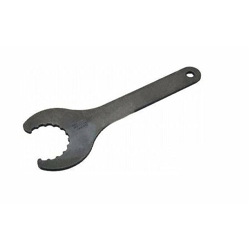
2) Always, always tighten the inner and outer lockrings with the correct tool. It's no good using pliers, grips etc, to tighten the inner nut and then hand tighten the outer one. The correct tool is cheap enough off eBay, so have one in your BBS toolkit.
 
If you don't mind the appearance, put a large hose-clamp around the motor housing, and that provides a band to use a smaller second hose-clamp to tie the first band to the downtube.
 
Interestingly, the Sunstar iBike (the forerunner to the BBSxx) used a combination of a torque arm, locking tab on the bottom bracket ring, and hose clamp around the motor body in order to prevent rotation. That seems like overkill for its rated 24V/250W.
 
The wattage doesn't really matter--it's the torque placed on the rotation center point; the leverage it can make on that.

Since you can shift gears between the motor output and the wheel, then if you have a high enough load (weight) on the wheel, and your gearing is sufficient between there and the motor, you can place a high enough torque load on the mounting's rotational point to require some form of "torque arm" to lock the mount in place relative to the frame.
 
alfantastic said:
Always, always tighten the inner and outer lockrings with the correct tool. It's no good using pliers, grips etc, to tighten the inner nut and then hand tighten the outer one. The correct tool is cheap enough off eBay, so have one in your BBS toolkit.

I think the dedicated BBSXX install tool is what you use when you don’t have easy access to the real thing, e.g.:

Full sized lockring pliers, like Hozan C-203
hozan-c-203-long-ring-pliers-9.gif


And a crow’s foot type spline tool for external bearing bottom brackets.
689228097421_512x512.jpg


In my casual observation, the cheap laser-cut tools are either flimsy (if open-ended) or likely to run out of operating clearance (if closed-ended).
 
There are some examples of fixtures on GrabCad,
https://grabcad.com/library/sunstar-ibike-motor-fixture--3

Apparently there was a design contest, to design a rotation stopper
for Sunstar: https://grabcad.com/challenges/sunstar-ibike-motor-fixture-challenge/entries
 
Back
Top