
You are using an out of date browser. It may not display this or other websites correctly.
You should upgrade or use an alternative browser.
You should upgrade or use an alternative browser.
tsdz2 OSF throttle not working
- Thread starter dirtgoon
- Start date
dirtgoon said:I have flashed my motor with the OSF for VLCD5 and can't figure out how to get the throttle working. I have a 48v motor with 36v battery, does anyone see any reason why it shouldn't be working?
Does the throttle correctly output the right voltage range? (around 0.8v-1v minimum without moving it, to around 3.5-4v maximum when turned to full on position)
Does the system operate correctly via pedals (torque sensor)?
If it works correctly from pedals, then the system itself is ok, possibly excepting the throttle wiring or connector. (doesn't exclude possible settings issues, such as a setting that is correctly set in the software but isn't writing to the controller correctly for some reason).
If there is nothing in the setup software or on the display menus that can show you the throttle voltage, you'd have to get to the wiring inside the controller (or elsewhere on the wiring harness as near to the controller as possible) and use a voltmeter to measure voltage between each of the three wires for the throttle (5v, ground, signal).
I don't know which pins inside the controller are for the throttle itself, but there should be info about that in the main TSDZ2 thread.
To get to the wiring in the harness, you would have to cut open the outer jacket to get the wires inside, so that's the last resort, generally. An extension cable could be installed temporarily, that is modified to access the wires inside it, to do the test with, but that's extra money just to do a test.
Ebikes.ca has some info on how to test sensors and such while disconnected from the controller, in their learn-troulbeshooting section. You may need a separate 5v supply, like an old USB-type phone charger, etc.
It is possible to check the adc values of the throttle input.dirtgoon said:I have flashed my motor with the OSF for VLCD5 and can't figure out how to get the throttle working. I have a 48v motor with 36v battery, does anyone see any reason why it shouldn't be working?
Thanks!
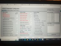
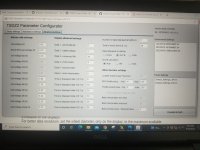
In the configurator, temporarily set:
Number of data displayed at lights on = 1
Data1 = 5 (adc throttle 8 bit)
Time to displayed data 1 = 0
Compile & Flash
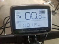
After turning on the display, turning on the lights with level 1 to 4, the adc throttle value is displayed.
Try to use the throttle, the value must change from 47 (minimum value), to 176 (maximum value).
If the value does not change, there is a wiring problem.
I flashed the motor again with the temporary settings. My display only shows MPH when I push the lights button, nothing changes when I push the throttle.
It's all brand new, controller, display, throttle, brake levers, everything.
Only conclusion I can come to is that the combination of components that I have just aren't compatible for use with a throttle.
It's all brand new, controller, display, throttle, brake levers, everything.
Only conclusion I can come to is that the combination of components that I have just aren't compatible for use with a throttle.
Attachments
With temporary settings, if operating the throttle with lights on, the displayed value is always zero, there is a hardware problem.
It is as if the throttle is not connected.
If you bought the components all in the same kit, they should be compatible with each other.
Try to check the 8 pin connector if it has a bent pin and if the throttle connector is inserted well, in the right direction and all the way.
If ok, you need to do more in-depth tests, but you need adequate knowledge and tools.
Matze_Senpai
100 W
- Joined
- Apr 16, 2022
- Messages
- 122
u did connect the throttle to the middle port right?
Yes throttle in the center, brake sensors on the outside. Bit of a pain to get snapped into place.Matze_Senpai said:u did connect the throttle to the middle port right?
Well things have gone from bad to worse. I swapped in a brand new 36v 8pin controller and flashed it with the OSF. Throttle still didn't work and now it reads only one bar on the battery monitor (the battery is at 42v), no wheel speed and reads no other parameters when the light button is pushed.
Soooo, I swapped back in the 48v controller because at least it WAS reading correct battery voltage, SOC and wheel speed. Now with that controller back in, the display is doing the same as the 36v controller, no wheel speed, one bar on the battery monitor and now no assist even with pedals. It seems I've managed to ruin two controllers and a display with this OSF.
Is there any way to undo the OSF now?
If no data from the controller is being displayed, it is likely there is a communication problem between them. Most likely it's a connection fault, probably on the TX line from the controller to the RX line on the display, either a pin not fully mating (bent pin, or barrel spread open, etc.), or a wire broken inside the connector housing or anywhere along the cable.
Since the problem happens with the same display but different controllers, the problem is likely within the display's cable or connector that goes to the controller.
Since the problem happens with the same display but different controllers, the problem is likely within the display's cable or connector that goes to the controller.
I probably just need to step away from this thing for a while. I feel like a dumb shit but part of the problem was that I didn't have the throttle and brake sensor cables snapped into place like I thought I did.
So I made sure they were fully seated and reflashed the 48v controller, the display is back to working properly and throttle now works *kind of*. It gives a burst of power (bike on stand) for 1-2 seconds then cuts back out.
So then I reflashed the 36v controller, the display is working but no throttle response at all.
With the 36v controller the ACD throttle value changes from 2.1 to 11.2 but does nothing.
Some thoughts about a couple of possible causes (that may not apply; there may be more info on this in the Github for the project, or it's wiki or threads; I have not checked):
I don't know how the firmware / flashing process is written for this OSF, but I've often enough run across devices (of all kinds) with firmware updates that flash the software, but not the *settings*, yet use incompatible settings data between the two FW versions. Some of them advise the user to reset everything to defaults manually, using whatever "factory reset" function there may be, but some don't.
Some may not have a settings reset function, but for those it may be possible to manually write values to all the fields to do the same job.
It would be more failsafe if they always actively reset all the settings fields (used or not) to defaults for that specific firmware at the same time, but this is not always done.
On occasion, some do a kind of reset, but they first check if a setting is already default and don't write to it if it is, yet somehow the setting is not really at that default (perhaps a single-bit difference where that bit isn't checked for some reason), so the corrupt or incorrect value persists and later causes a problem with the firmware trying to read it back and use it to do things with. Some may not check any settings but may only write to a few of the locations, attempting to preserve user-settings or "calibration" values, that end up being incompatible with the new FW.
So if there is the option to do a full reset, something that actively writes that specific firmware version's default settings data to *all* settings (including all fields regardless of what they are for), it might fix a problem caused by this particular issue.
It would force you to set every setting back up again, but if it works, it's worth the time.
Another potential issue is if there are files with your settings being used to reset the device to particular setups, *those* could have incompatible (or corrupt) values within them causing problems. Ensuring you manually change each field in the setup software to the correct new data (perhaps even changing each field that appears already correct to something else, then back to the known-correct value, before flashing the new settings) might work.
Be sure to check the connector end on your current motor/controller system to verify if it has 8 pins. You will need to match it to install the VLCD-5 Display. This Display/Throttle/E-Brake Bundle is ONLY COMPATIBLE WITH TSDZ2 SYSTEMS THAT HAVE AN 8 PIN CONNECTOR!
Similar threads
- Replies
- 9
- Views
- 379
- Replies
- 5
- Views
- 402