HV110 disection and expansion

recumpence

1 GW
Joined
Apr 19, 2008
Messages
5,304
Location
On Earth right now. That can change at any time, t
Hey Guys,

This thread is dedicated to discussing the possibility of expanding the Castle Creations HV110 with more FET boards.

I spoke with Castle Creations, as well as a number of electronic engineers about this and have gotten mixed information.

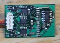
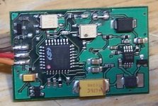
What I am specifically looking at is stacking one or two more FET boards onto one HV110 controller board. You can see the 15 pin connector on the controller baord. That 15 pin connector is a pass-through connector on each of the HV110 FET boards. Each old style HV110 FET board uses 18 FETs per side for a total of 108 FETs on the 3 boards. The newer HV110s use 12 larger FETs per board side for a total of 72 larger FETs total. It would be quite easy to take a spare HV110 and remove one or more FET boards to be paralelled for a 4, 5, or 6 board HV controller. The issue with doing this is the current available to drive more FET gates. To that end, I attempted to take a picture of each side of and old (bad) HV110 controller board to see if it looks like it would be capable of driving more FETs.

Excuse the pic quality. My camera is not very good at close up shots. I can try for some better shots in better light if need be.

Anyway, who has thoughts on this?

Matt
 
I don't see a problem other than the one you stated. The FET driving circuit has a finite current limit, and each additional FET adds gate capacitance. There is a finite limit to how many it will be able to turn on simultaneously without blowing up.

What did CC say? I would think they would know more about doing this than anyone else...

Do you really need more current capacity? :twisted:
 
oofnik said:
I don't see a problem other than the one you stated. The FET driving circuit has a finite current limit, and each additional FET adds gate capacitance. There is a finite limit to how many it will be able to turn on simultaneously without blowing up.

What did CC say? I would think they would know more about doing this than anyone else...

Do you really need more current capacity? :twisted:

Then we can probably by-pass them on the original board and put more gate driver on the new Mosfet board...?
 
matt,

can you get a close shot of the gate driver ic?

one way is to replace the gate drive ic with a higher drive current one and then stack those fet boards...
but it will be easier to just make a new board complete with gate driver and "better" mosfet and use the hv control board

my prof often said "less chips = less points for failure"

russ
 
i did the similar stuff to one of the industrial motor controllers, what i did was
1. first add more mosfets to the controller without changing the gate driver
2. see if the gate signal slew rate degrades, if it did, then stack another same gate driver on the old one to double the gate driver strength.
3. sometimes two gate drivers might be too much a load for the micro controller output pin, then you have to insert a buffer b/t the gate driver input pin and the micro controller output pin. nevertheless this should rarely happens.

can you find out the gate driver part number of this HV controller? this might be crucial to this mod.
also, it is possible to expand the operating voltage. for mosfet motor controllers, 100V is quite a barrier but should be reasonably easy to accommodate. mosfets rating is not a problem as it's easy to find 200V rated mosfets. it is the voltage regulator circuit that might not withstand 100V input. you might want to serialize another BJT to drop out more voltages before it reached the final voltage regulator like a 7805.

be very careful about the gate signal slew rate, you could easily fry out the mosfets if the slew rate is slow!

-george
 
oofnik said:
What did CC say? I would think they would know more about doing this than anyone else...

Do you really need more current capacity? :twisted:

Castle is a weird company in that when you talk to them, you will get conflicting answers. For example, when I asked them about stacking another FET board, they insisted they could not do it. They told me the driver will not handle more FETs. However, another tech from there told me they can do it for an upcharge. Also, a few guys on RCMonster forum (big monster truck guys) have these so called HV160 modded controllers with more FETs in their trucks. But, when I asked Bernie from Castle about it, he told me emphatically "It will not work!". That being said, he also insisted adding caps would not help my controller issues and he was wrong.

I think what is going on is a liability thing. They know we are using these for human propulsion and they are NOT happy with that.

Oofnik,

The HV110 is rated for 5kw. However, I have found them somewhat unwilling to put out more than 3kw repeatedly without blowing even with added input caps.

I really want a consistant 5kw output. :mrgreen:

Matt
 
georgeycc said:
1. first add more mosfets to the controller without changing the gate driver
2. see if the gate signal slew rate degrades, if it did, then stack another same gate driver on the old one to double the gate driver strength.


This is the right approach. This is what I did on the Crystalyte controllers. You can check the gate signals with an oscilloscope before and after. The motor does not need to be loaded for this test.

I don't think you'll get 5kw out of that little thing for more than a few seconds. It needs much more thermal mass and heat sink to sustain a level like that. Putting a blower aimed at the existing heat sink would help quite a bit, similar to how they cool CPUs.

After I get done tuning my throttle interface gizmo, I plan to dissect mine to take a look inside.
 
I have pulled 7kw from mine on my recumbent and it was fine for 100 miles of riding relatively hard. However, it blew. Hmm, I began keeping it under 5kw. It still blew after 100 miles. I went to 3kw and it blew, again, after 100 miles. Then I added caps. Now I have 300 miles on one without a problem.

I think you are correct about cooling. I am adding fans to my next build ESC.

Matt
 
The thing about Castle is that Patrick (the CEO/Owner..) is the only engineer. Bernie and Joe are just techs, with little theorectical knowledge. I would not take what Bernie/Joe say as gospel, by any means.
 
The problem with Castle ESC's is that each connector is a failure point. If you add 2 more boards you have 2 more connectors which could fail. It would be a better idea to start off with something a little more substantial, and work from there. Making an HV-200 with 5-6 boards would be a kludge of a design imho. Even so, it would be interesting to see if it could work.......
 
Matt-

Please get some photos of the driver chips! I'm seeing some distant fuzzy blocks, but nothing that will help me know how much load the drivers can handle.


Set your camera on highest resolution. Strong light source at an angle that doesn't cause glare to your camera. You can hold a magnifying lens in front of your camera lens to help it focus at a closer distance. Set your camera to macro mode (little flower picture). Since the photo will have more more pixels than it needs to map the display 1:1, crop away everything but the circuit board from the picture, and it will make better use of available resolution when you host the photos for us. Even the worst camera can take pretty good macro shots if you do these things.
 
Hi Matt,

recumpence said:
I have pulled 7kw from mine on my recumbent and it was fine for 100 miles of riding relatively hard. However, it blew. Hmm, I began keeping it under 5kw. It still blew after 100 miles. I went to 3kw and it blew, again, after 100 miles. Then I added caps. Now I have 300 miles on one without a problem.

300 miles at 5kw or 3kw?

recumpence said:
I think you are correct about cooling. I am adding fans to my next build ESC.
Matt

A big finned heat sink would be nicer than a fan if it worked.
 
300 miles of VERY frequent 3kw pulls and the occaional 5kw run. I have a few hills here that require 3kw to climb at 30mph. So, I am up at that threshold numerous times per ride.

Matt
 
Less typing and more picture taking :)
 
liveforphysics said:
. You can hold a magnifying lens in front of your camera lens to help it focus at a closer distance..

I use a jewelers loop with my camera
I can snap pictures pictures of solder joints and see every little pit and imperfection.

-methods

EDIT: I forgot to mention the most important part: My camera is a CELL PHONE
 
Nice shot Methy! That's a damn good macro shot for a cell phone camera! LOL
 
Matt, can you get a part number of any of the FETs? I''d like to figure what the true voltage limit is for these controllers.

The mod I'd like to see for these controllers is to increase the voltage allowed. I think 110A is plenty, but I'd love to see one that would also do 70-80V. I know this is not probably feasible, since the FETs are more than likely the limiting factor. I wonder if the FET boards can simply be replaced with something like a modified FET board from a Clyte controller, like Richard mentioned doing.

-- Gary
 
The new controllers use different FETs. I will check and see if there is a part number on them, though.

Sorry I haven't posted better pics yet. I was in a wedding yesterday (running sound). So, I have not been available.

I will post better pics today.

Matt
 
Make sure to get some good pics of the FET driver board as well as the FET boards :) Thanks!
 
Here are a couple pics of the controller board.

I will have to take a few of the FET board as well.

Anyway, this is the best I could do. I can try a few more setting changes later if I have the chance.

Matt
 

Attachments

  • escboard1.jpg
    escboard1.jpg
    31.9 KB · Views: 2,179
  • escboard2.jpg
    escboard2.jpg
    46.4 KB · Views: 2,179
OK - blew up my first one. Gave it 54V and POOF! Like in the original Batman TV series. Big sound, big smoke! :shock:

Now I have a request of all those electronically gifted folks here:

Can someone show me a simple circuit that could protect the HV110 from over-voltage damage like that?


Some kind of gate that won't let over 50V through.

I don't care if it just says "beep" to tell me NO.

Sigh.
 
Back
Top