12p3phPMDC
1 kW
- Joined
- Mar 16, 2009
- Messages
- 462
I'm starting this thread to help explore the idea of running a 3 phase 12 pole RC outrunner motor as split phase or dual stator. Luke brought up the idea in the "attaching hall sensors to RC motors" thread.
In the paper by Lyra and Lipo, they describe a type of 6 phase machine like this in the introduction:
A particular case of split-phase or dual-stator machine, the
six-phase machine can be built by splitting a three-phase
winding into two groups. Usually these three-phase groups
are displaced by thirty electrical degrees from each other.
This arrangement composes an asymmetrical six-phase
machine since the angular distance between phases is not all
the same [6]. The analysis of an induction machine for
multiple phases and arbitrary displacement between them is
presented in [2] where the six-phase induction machine is
used as an example and an equivalent circuit has been
derived. The dq0 model for a six-phase machine was
developed in [7].
Reliability is one of the advantages in using six-phase
systems. In the case of failure of one of the phases, either in
the machine or in the power converter, the system can still
operate at a lower power rating since each three-phase group
can be made independent from each other.
and then later under System description:
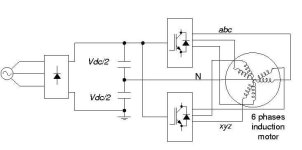
An experimental setup was built to test the proposed
technique. Fig. 7 shows the setup configuration. A common
DC link is used for two three-phase inverters connected to
each winding group of the six-phase machine. The neutral is
connected to the mid point of the DC link capacitors. An
additional inverter leg is provided for future investigation on
the neutral current direct control.
Ok, wow, that's quite a mouthful. But, I think that it applies to the high pole count 3 phase motors that we are running!!
Here's a link to the thread that got me going on this:
viewtopic.php?f=28&t=9061&start=60#p147898
and the paper
http://www.ece.wisc.edu/~lipo/2002pubs/2002_12.pdf
Ok, so to spur this on, I bought two of the Turnigy 12S 120V units, and another HXT 130 kv.
I bought the 130 kV vs. the 180 kV version because, I was thinking about the windings and
what splitting the stator would do to the resistance. They claim a 32 ohm winding, and if you
split the phases into two parallel 6 pole sets, then you'll probably end up with two 16 ohm windings.
Well, the 180 kV motor runs 17 Ohm windings....so this should keep coil resistance high enough.
Luke, you said you'd be able to help if we have a game plan, so here goes....
1. Figure out how to unwind/wind the stator in two 6 pole 3 phase sets (abc delta,xyz delta)
2. Come up with a load cell. This will be the most mechanical work, i.e. poor mans dyno
3. Instrument up the current from batteries/phases....measure voltage and current at all times.
4. Obtain batteries... Lead acid banks for cost, or 12S LiPo @ 2.5 AH, 30C cells?
(my 6S Lipo 5 AH Zippy cells are still in backorder!!!!)
5. Try not to saturate the stator or demagnitize the magnets!! (i.e.nonlinear output at peak or diminishing output after every run)
(plan needs more development)
Fun, fun, fun!!!
In the paper by Lyra and Lipo, they describe a type of 6 phase machine like this in the introduction:
A particular case of split-phase or dual-stator machine, the
six-phase machine can be built by splitting a three-phase
winding into two groups. Usually these three-phase groups
are displaced by thirty electrical degrees from each other.
This arrangement composes an asymmetrical six-phase
machine since the angular distance between phases is not all
the same [6]. The analysis of an induction machine for
multiple phases and arbitrary displacement between them is
presented in [2] where the six-phase induction machine is
used as an example and an equivalent circuit has been
derived. The dq0 model for a six-phase machine was
developed in [7].
Reliability is one of the advantages in using six-phase
systems. In the case of failure of one of the phases, either in
the machine or in the power converter, the system can still
operate at a lower power rating since each three-phase group
can be made independent from each other.
and then later under System description:
An experimental setup was built to test the proposed
technique. Fig. 7 shows the setup configuration. A common
DC link is used for two three-phase inverters connected to
each winding group of the six-phase machine. The neutral is
connected to the mid point of the DC link capacitors. An
additional inverter leg is provided for future investigation on
the neutral current direct control.
Ok, wow, that's quite a mouthful. But, I think that it applies to the high pole count 3 phase motors that we are running!!
Here's a link to the thread that got me going on this:
viewtopic.php?f=28&t=9061&start=60#p147898
and the paper
http://www.ece.wisc.edu/~lipo/2002pubs/2002_12.pdf
Ok, so to spur this on, I bought two of the Turnigy 12S 120V units, and another HXT 130 kv.
I bought the 130 kV vs. the 180 kV version because, I was thinking about the windings and
what splitting the stator would do to the resistance. They claim a 32 ohm winding, and if you
split the phases into two parallel 6 pole sets, then you'll probably end up with two 16 ohm windings.
Well, the 180 kV motor runs 17 Ohm windings....so this should keep coil resistance high enough.
Luke, you said you'd be able to help if we have a game plan, so here goes....
1. Figure out how to unwind/wind the stator in two 6 pole 3 phase sets (abc delta,xyz delta)
2. Come up with a load cell. This will be the most mechanical work, i.e. poor mans dyno
3. Instrument up the current from batteries/phases....measure voltage and current at all times.
4. Obtain batteries... Lead acid banks for cost, or 12S LiPo @ 2.5 AH, 30C cells?
(my 6S Lipo 5 AH Zippy cells are still in backorder!!!!)
5. Try not to saturate the stator or demagnitize the magnets!! (i.e.nonlinear output at peak or diminishing output after every run)
(plan needs more development)
Fun, fun, fun!!!