Beltbox?

Joined
Sep 28, 2019
Messages
61
Location
Los Angeles
I've been trying to design a gearbox around the Neumotor 8057 to drive the chainwheel from an all internal assembly a'la BBSHD. Every otherwise workable design I finish has the same unnacceptable flaw: it weighs a ton. However, I've been following an older thread on here involving a single reduction of this motor using a Gates GT2 belt system.

https://endless-sphere.com/forums/viewtopic.php?f=30&t=91144&hilit=8057

At first glance, a two stage belt reduction using a similar system seems like an excellent solution. Gt2 and 3 sprockets are readily available in aluminum. Belts are relatively light. And the first draft of the design is honestly simpler than anything yet: two-stages of 62:14, with the final sprocket bored for a spragg clutch around the bottom bracket axle, yielding a quiet and simple (roughly) 20:1 reduction.

Much more talented designers than me have not utilized such a system. So I have to be missing something. What is it? What am I missing? Why is this suboptimal? Surely my inexperienced 'duh just use two belts' is a headsmackingly dumb idea. But why? Roast me!
 
Browse uses belts and in considered one of the quietest factor EMTBs.

What sort of frame is this going on? Does it need to have pedals?
 
Its not a dumb idea and you don't deserve a roast. It is a formidable engineering challenge. The secret to any of these high RPM mid drives is understanding the interplay between torque, power, and RPM. It's easy to get beyond common off the shelf belts and pulleys as well as end up with impractical sized pulleys for your bike. Also, when you get above 3kw through the crank drivetrain you are really stressing components. Lots of people do it and its fun but be ready to replace some stuff often. Bike drivetrains are usually overdrive ratios at comfortable cadence so running 7-10 hp from a neumotor 80xx at 100rpm cadence would require motorcycle size chain since its motorcycle sized torque at that point.

Here is a truly ball park estimate of what you are proposing but it should give you an idea how to work out the math with your particular specs.
Lets say you pick a motor wind to make 7hp or 5200watts at 6000rpm.

2 stages of reduction each at 62:14 (approx 4-1/2 to 1)
That gives you 4.5 x 4.5 = 20.25 to 1

If you are making 5200watts at 6000 rpm that is 8.25Nm of torque output from the motor according to this handy calculator online.http://wentec.com/unipower/calculators/power_torque.asp

Next you multiply that torque by your ratio after your 2 reductions and you are at 167Nm of torque.
8.25Nm X 20.25=167.0625

From there you pick a sprag clutch. A csk35 sprag bearing is rated to about 140 Nm but its 72mm diameter and weighs almost a pound! Assuming you find a way to package all of that at the crank you are now likely overdriving the bike drivetrain meaning your pedal sprocket is larger than the wheel sprocket. So once again we multiply the torque.

Lets say you have a 36 tooth chainring and a 22 tooth cog at the rear wheel. Now the torque gets even crazier:
167Nm X (36/22)=273Nm
This is definitely motorcycle chain territory.

The people that get away with these levels of power on bicycle chain use very small drive sprockets and very large driven sprockets to keep the force on the chain low enough. Same goes for gates belts. Using a single speed reduction you can get it all done in one stage without stressing the belt. The problem is the massive disparity between human leg RPM at the crank and motor rpm. If you run a 17 tooth pedal sprocket and a 60 tooth wheel sprocket you can keep the chain happier but forget about pedaling faster than 2 mph before your cadence becomes impossible.

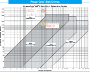
One last thing with regard to gates GT2 belts. Here is a chart from their design guide that helps illustrate the point a little better. Using my guestimates about your motor choice and power level (7hp and 6000rpm) you could use 5mm pitch belt for the first stage but you would need 8mm pitch belt for the 2nd stage in your box. A 62 tooth pulley of 8mm pitch is likely 7 inches in diameter.

If you must design your own system to get to reasonable pedal cadence I'd recommend you pick a way less powerful motor than the neu 8057 and consider using a 5mm pitch primary and maybe a 219 chain secondary. You may be able to get most of the reduction done at the primary and rely on the heavy pull strength of the 219 chain to do the heavy lifting at the secondary. You may have to give up on the idea of pedaling along with it and just accept that you have built a motorcycle. If you give up on pedaling you can buy a massive 50 tooth rear cog that will fit a standard mountainbike cassette.

Hope that all helps a little. Seems more constructive than roasting you. :D
Power grip math.png
 
nowholeself said:
Much more talented designers than me have not utilized such a system. So I have to be missing something. What is it? What am I missing? Why is this suboptimal? Surely my inexperienced 'duh just use two belts' is a headsmackingly dumb idea. But why? Roast me!

I believe the problem or the reason why two-stage belt drives aren't used widely might be that they take so much space, space which could have been used instead for a larger motor with more torque.

Whats your desired torque, or power? The 8057 can do around 15-20Nm continuous (in my case with my components/setup) so you can expect around 400Nm at the crank with 20:1 which would be quite a bit^^
Do you own the motor already?
 
DanGT86 said:
Its not a dumb idea and you don't deserve a roast. It is a formidable engineering challenge. The secret to any of these high RPM mid drives is understanding the interplay between torque, power, and RPM. It's easy to get beyond common off the shelf belts and pulleys as well as end up with impractical sized pulleys for your bike. Also, when you get above 3kw through the crank drivetrain you are really stressing components. Lots of people do it and its fun but be ready to replace some stuff often. Bike drivetrains are usually overdrive ratios at comfortable cadence so running 7-10 hp from a neumotor 80xx at 100rpm cadence would require motorcycle size chain since its motorcycle sized torque at that point.

Here is a truly ball park estimate of what you are proposing but it should give you an idea how to work out the math with your particular specs.
Lets say you pick a motor wind to make 7hp or 5200watts at 6000rpm.

2 stages of reduction each at 62:14 (approx 4-1/2 to 1)
That gives you 4.5 x 4.5 = 20.25 to 1

If you are making 5200watts at 6000 rpm that is 8.25Nm of torque output from the motor according to this handy calculator online.http://wentec.com/unipower/calculators/power_torque.asp

Next you multiply that torque by your ratio after your 2 reductions and you are at 167Nm of torque.
8.25Nm X 20.25=167.0625

From there you pick a sprag clutch. A csk35 sprag bearing is rated to about 140 Nm but its 72mm diameter and weighs almost a pound! Assuming you find a way to package all of that at the crank you are now likely overdriving the bike drivetrain meaning your pedal sprocket is larger than the wheel sprocket. So once again we multiply the torque.

Lets say you have a 36 tooth chainring and a 22 tooth cog at the rear wheel. Now the torque gets even crazier:
167Nm X (36/22)=273Nm
This is definitely motorcycle chain territory.

The people that get away with these levels of power on bicycle chain use very small drive sprockets and very large driven sprockets to keep the force on the chain low enough. Same goes for gates belts. Using a single speed reduction you can get it all done in one stage without stressing the belt. The problem is the massive disparity between human leg RPM at the crank and motor rpm. If you run a 17 tooth pedal sprocket and a 60 tooth wheel sprocket you can keep the chain happier but forget about pedaling faster than 2 mph before your cadence becomes impossible.

One last thing with regard to gates GT2 belts. Here is a chart from their design guide that helps illustrate the point a little better. Using my guestimates about your motor choice and power level (7hp and 6000rpm) you could use 5mm pitch belt for the first stage but you would need 8mm pitch belt for the 2nd stage in your box. A 62 tooth pulley of 8mm pitch is likely 7 inches in diameter.

If you must design your own system to get to reasonable pedal cadence I'd recommend you pick a way less powerful motor than the neu 8057 and consider using a 5mm pitch primary and maybe a 219 chain secondary. You may be able to get most of the reduction done at the primary and rely on the heavy pull strength of the 219 chain to do the heavy lifting at the secondary. You may have to give up on the idea of pedaling along with it and just accept that you have built a motorcycle. If you give up on pedaling you can buy a massive 50 tooth rear cog that will fit a standard mountainbike cassette.

Hope that all helps a little. Seems more constructive than roasting you. :D
Power grip math.png

Thank you for this response! I love it for a few reasons. It confirms most of the numbers I've calculated. It offers some insights. And it rightly demonstrates that I'd be making more of a motorcycle than a bicycle. That's what my current BBSHD ride is like and I love it. No pedal assist. No display. Single gear. Just pedal out of the gate, throttle and go. I should mention a couple details though. One is that the gearbox (or beltbox) is meant to accommodate a variety of engines the size of an 8057 or smaller. I'm designing it around the 8057, but the idea is to make a single assembly that allows options. It just strikes me as odd that these boxes are made without the ability to swap engines and maybe an internal gear ratio as well. Also, if I were personally to use the 8057, I'd be running it at 52v with not even half of the current it could take. So I wouldn't be achieving the rpms and torque calculated above. Chances are, I'll run an 8038 instead. Did I mention I'm designing a titanium bike frame as well? :D
 
madin88 said:
nowholeself said:
Much more talented designers than me have not utilized such a system. So I have to be missing something. What is it? What am I missing? Why is this suboptimal? Surely my inexperienced 'duh just use two belts' is a headsmackingly dumb idea. But why? Roast me!
I believe the problem or the reason why two-stage belt drives aren't used widely might be that they take so much space, space which could have been used instead for a larger motor with more torque.

Whats your desired torque, or power? The 8057 can do around 15-20Nm continuous (in my case with my components/setup) so you can expect around 400Nm at the crank with 20:1 which would be quite a bit^^
Do you own the motor already?

I don't own the motor already. Even though I'm designing the box to accommodate it, I'll likely go with a smaller 100kv engine like the 8038, and running it at 52v with 45amp continuous 21700 cells. The performance of these engines is insane. I'd prefer 200nm continuous at the crank. I've been assuming that running such engines with only the wattage necessary to achieve lower numbers will make for less heat, high reliability, and an acceptable amount of wear and tear on the drivetrain. But perhaps there's a performance disadvantage to running this way. If so, please let me know!
 
Not to over generalize here but usually attempts to cheat physics by playing the kv game don’t work out so well. Try to think of the kv only as a way to match the motor to the voltage and nothing else. There are some differences in efficiency between different windings but the rpm required to make power doesn’t change much. Sorry if I’m telling you stuff you already know here. Lots of people think they can get a lower kv motor and make the same power at lower rpm.

It sounds like you have some ambitious goals with the titanium frame and gearbox so I’m assuming you have some manufacturing capability. I hope you do because more than one person has posted about the Neumotor needing some work right out of the box regarding the shaft and bearing fitment.

To weigh in with strictly opinion here, I’d suggest you try and get it done in one reduction. If you understand that you are building a motorcycle then leave the pedals alone and drive it on the left side via the disk brake flange. You can send massive power there with any type of chain or belt you want and you still have all your bike gears working properly on the right side.
Years ago there were few options for stuff like this so people were messing with multi stage reductions and tiny RC motors. They are still cool and I still nerd out over them but as many people will tell you its better to add weight as working copper in the motor compared to gear reductions that just take power to spin.

Madden’s setup is a perfect example of how much fun you can have with a neumotor and single stage to the wheel.
If you are curious feel free to check out my RC motor gates belt reduction thread. For what its worth I decided to sell it after the first test ride. Building it was the fun part but I bought an LMX motor on the sale they are currently running and it’s 45kv and 1500 watts continuous. It will accomplish the same thing without the delicate belt reduction setup.

http://www.endless-sphere.com/forums/viewtopic.php?f=28&t=87934&sid=a2480374c0499a6093cdcdf6e1bf4621
 
DanGT86 said:
Not to over generalize here but usually attempts to cheat physics by playing the kv game don’t work out so well. Try to think of the kv only as a way to match the motor to the voltage and nothing else. There are some differences in efficiency between different windings but the rpm required to make power doesn’t change much. Sorry if I’m telling you stuff you already know here. Lots of people think they can get a lower kv motor and make the same power at lower rpm.

It sounds like you have some ambitious goals with the titanium frame and gearbox so I’m assuming you have some manufacturing capability. I hope you do because more than one person has posted about the Neumotor needing some work right out of the box regarding the shaft and bearing fitment.

To weigh in with strictly opinion here, I’d suggest you try and get it done in one reduction. If you understand that you are building a motorcycle then leave the pedals alone and drive it on the left side via the disk brake flange. You can send massive power there with any type of chain or belt you want and you still have all your bike gears working properly on the right side.
Years ago there were few options for stuff like this so people were messing with multi stage reductions and tiny RC motors. They are still cool and I still nerd out over them but as many people will tell you its better to add weight as working copper in the motor compared to gear reductions that just take power to spin.

Madden’s setup is a perfect example of how much fun you can have with a neumotor and single stage to the wheel.
If you are curious feel free to check out my RC motor gates belt reduction thread. For what its worth I decided to sell it after the first test ride. Building it was the fun part but I bought an LMX motor on the sale they are currently running and it’s 45kv and 1500 watts continuous. It will accomplish the same thing without the delicate belt reduction setup.

http://www.endless-sphere.com/forums/viewtopic.php?f=28&t=87934&sid=a2480374c0499a6093cdcdf6e1bf4621

Do you mean this motor: https://lmxbikes.com/en/drivetrain/192-moteur-lmx-60mm-2018.html

It looks cool. Would love to see your build.
 
Yeah, thats the motor. 1500 truly continuous isn't too bad on a bike. If it can peak to 3-4kw I'll be happy with that. Anymore becomes a bit tricky on tight mountainbike trails.

That motor is about the same size as my whole reduction drive. Its low enough kv for me to rig up a bottom bracket pedal drive some day, and its relatively mud/water proof compared to the gates belt drive.

Sale thread is here.
http://www.endless-sphere.com/forums/viewtopic.php?f=31&t=99040&sid=08407b536e86c4c47fbd82f5461341e8

Build so far is the one I linked in the last post. I havent posted anything on the LMX motor yet.

Sorry if it sounds like I'm trying to talk you out of your plan. Having been there and done that with the belt reduction I have realized how much fun can be had being lazy and just getting a bigger motor.
 
Definitely go left hand drive. You could use a belt reduction to the bottom bracket then a chain to the rear. Would significantly reduce noise to have a lower chain speed.
 
Since we're talking LH drives, this is one of the most clever uses of space i've seen. Could be good for some inspiration.
https://endless-sphere.com/forums/viewtopic.php?t=82678
 
Total motor noob here trying to wrap my head around these ideas.

How does this topic relate to what've been called "outrunner" motors elsewhere?

Links to more successful detailed build threads would be appreciated.
 
In a permanent magnet brushless motor the wires are wound around the stator which doesnt move. The magnets are attached to the rotor which is where the output comes from.

Outrunners are motors where the magnets spin around the outside of the stator. Many RC hobby motors are like this. Hub motors are also built this way.

Inrunners are opposite that such that the magnets and the rotor are inside of the stator. So the whole center of the motor is the spinning part. The outside is stationary.

It gets confusing because many small outrunners have a shaft that passes through the middle and is used for the output torque. From the outside they can look like inrunners. If the whole outside spins then its an outrunner.

Im short the name out/in runner is the location of the magnets with respect to the stator.
 
OK thanks, I had inferred had to do with where the motor is mounted, like when hub motors are used as mid-drives up above the BB.

Is there a term for that, not hub mounted, not BB mounted?

So much to learn. . .
 
Bottom bracket mount are considered mid-drives. Its just a common location to hang a motor.

A hub motor mounted anywhere other than a wheel would Be considered a mid-drive and be found in the non hub motor section of the forum.

As far as I know all hub motors on the market are outrunners. There are some builders here who have converted geared hub motors such that the case is stationary and mounted to the frame and the axle becomes the output shaft. Technically this is still an outrunner because the magnets still spin outside of the stator windings but from the outside it would look like an inrunner.

https://endless-sphere.com/forums/viewtopic.php?t=45245
 
Back
Top