gap between swing arm and disc brake -- suggestions?

owhite

100 W
Joined
Aug 3, 2020
Messages
285
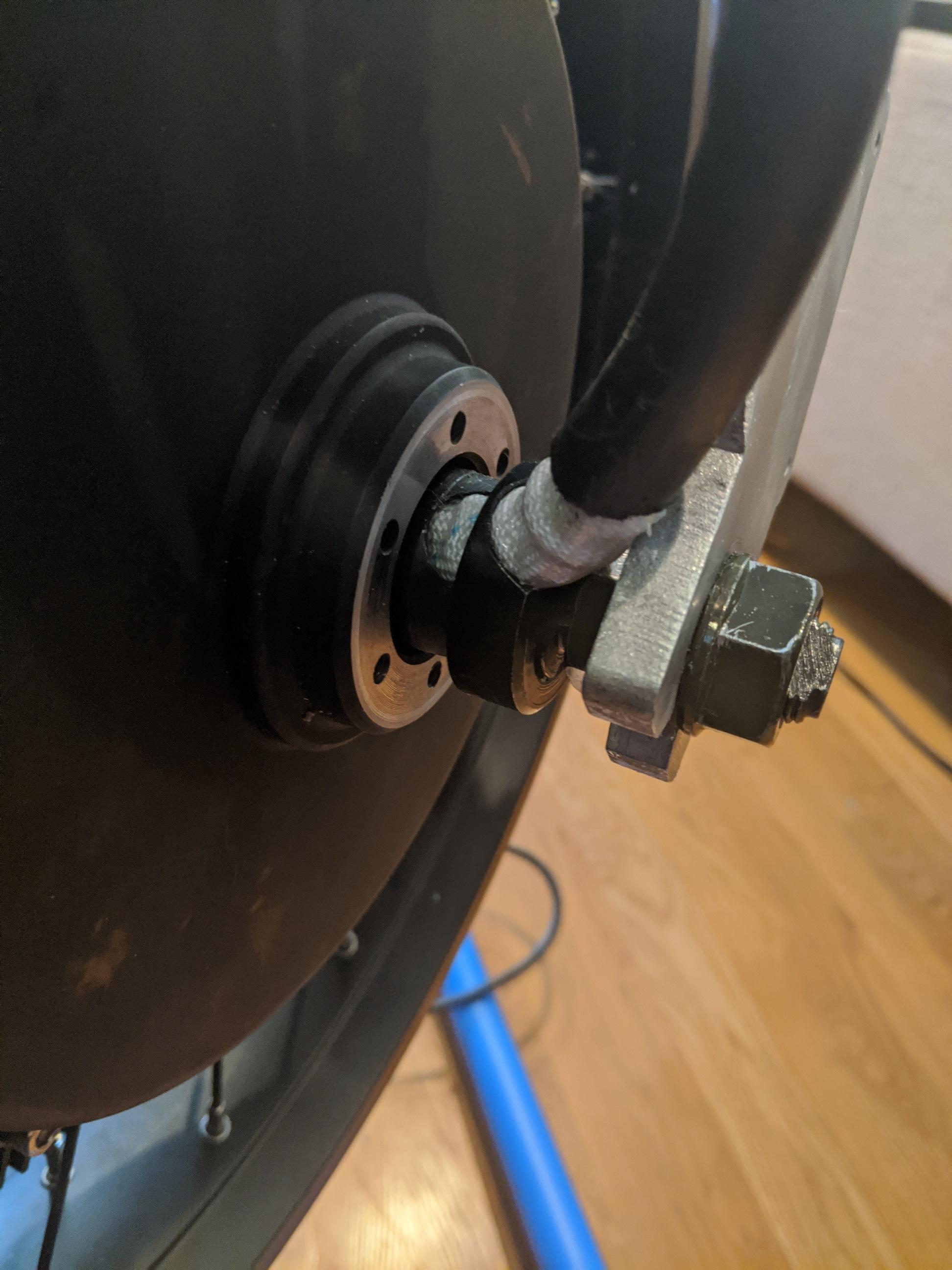
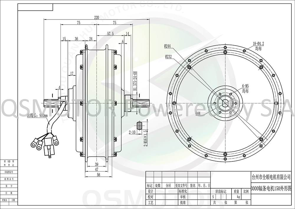
I made a custom swing arm with a 190 dropout distance for a QS205 motor. Swing arm construction described here:
https://endless-sphere.com/forums/viewtopic.php?f=6&t=108357&p=1612317#p1595747
Next time i'll design the distance differently.

nEJtZwR.png


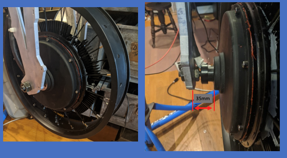
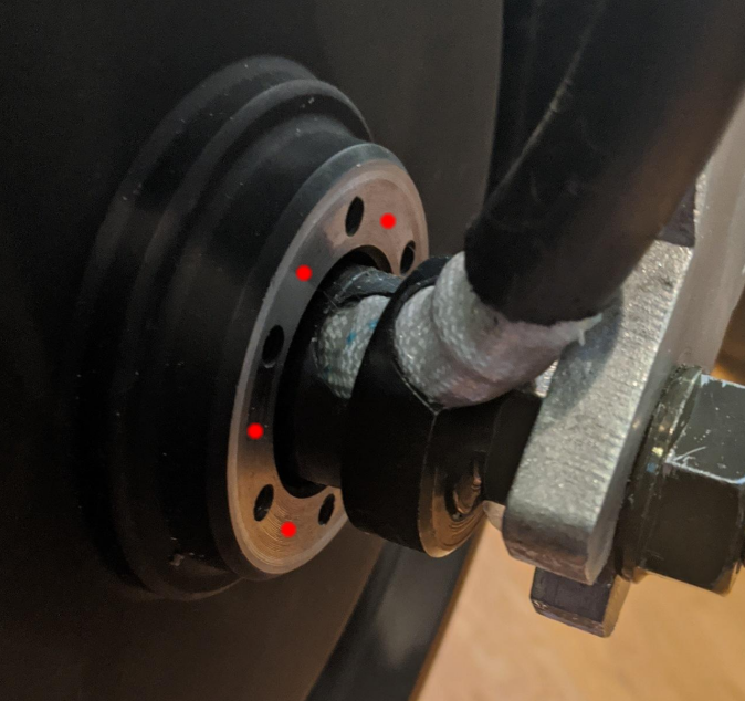
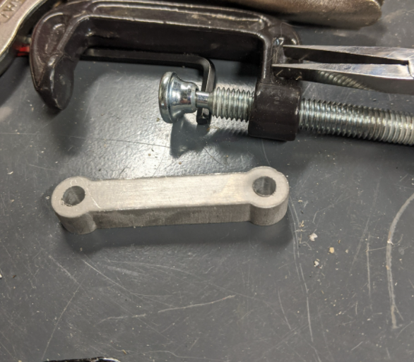
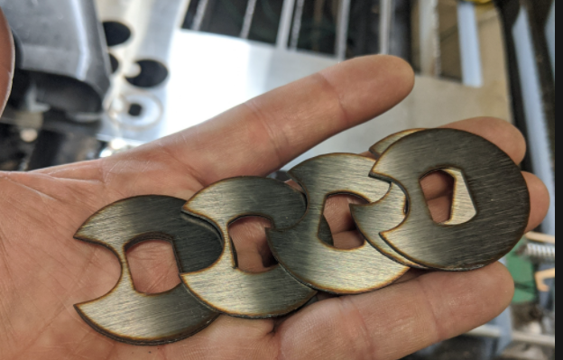
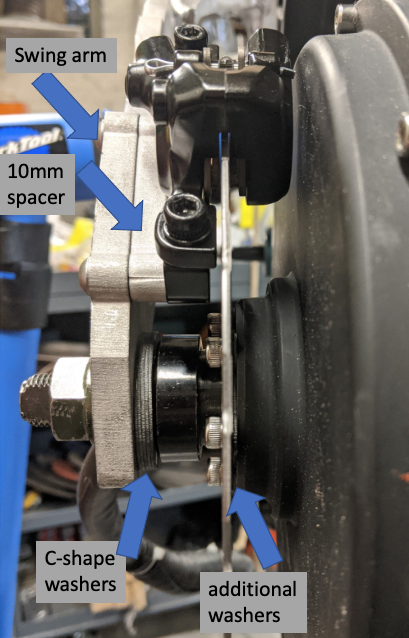
so I have a gap of 35mm between the swing arm and the bolt plate for the brake disc. What are my options for matching the brake caliper to the disc? I could build out the distance between the QS205 mounting area, and/or build an adaptor that meets between the caliper and the swing arm. I have lots of machining options, but I'm just curious....

How do most people address/deal with this?

thanks for suggestions!
 
Spacing the rotor is more robust than spacing the caliper, when you have that much gap especially. I mean, a spacer that is that thick is stiffer when held with 6 screws than 2. You’d have to make it anyway, unless you are willing to combine many of them that are available ready made.

s-l300.jpg
 
owhite said:
so I have a gap of 35mm between the swing arm and the bolt plate for the brake disc
So you don't need a full 35mm offset though. The caliper mount face will be outboard of the disc mount face by some amount (you should measure).

For arguments sake, say the caliper mount is 10mm offset from the disc mount, so the total offset required is 35-10=25mm.

No way I would use a spacer to offset the disc that much. The hub is made of cheap cast aluminium with negligible quality control. The disc bolts are small (M5 or M6 ?). The added offset puts additional moment on the joint which increases the shear and tensile load on the screws. I would not risk that extra load on the hub threads based on a questionable material with small screws and short thread engagement.

Instead I would make an nice offset block for the caliper, and where it fixes to the swingarm I would increase those bolts to M8 and drill out the swingarm to suit. Then the joint which takes most of the load is stiffer and stronger.
 
I do see your point about torque, but from a physics perspective, isnt there more torque placed on the just two bolts, that are ~180mm from the center of the axle, as compared to six bolts that are closer?

the bolts off the hub are M5s.

you make a good point which is if the hub bolts get shredded, repair will be very difficult - it would be easier for me to fix anything that happens to the M8s up on the swing arm. My intuition is the caliper is more likely to shudder or chatter if they're on some kind of riser, but that's just my intuition.

I'm almost wondering about a combination of yours and Mad Rhino that splits the difference between but the hub and the swing arm.
 
The cover of a qs205 is thick and strong enough. That is a 30 lbs motor with no effort made to save weight. The spacer/adapter required for bicycle rotors was included with the first versions of this motor that had a motorcycle rotor drilling pattern. The spacer-adapter was about one inch thick. I used it with 225 mm rotors and big calipers, never broke anything, repeatedly stopping hard from 60 mph.

Spacing a caliper that much does make it move out of alignment in hard braking, because 2 long screws are making an easy twisting under torque. A custom offset caliper mounting bracket does it too, but more work and precision machining required.

Anyway, try what you want. After a few builds you will end up with the easier, cheaper, stiffer, disc spacing solution.
 
Bond or bolt a plate on the inboard side of the current caliper bolt holes of the swingarm so that the longer screws aren't affected under braking (no twisting, just the regular sheer forces).
 
serious_sam said:
No way I would use a spacer to offset the disc that much. The hub is made of cheap cast aluminium with negligible quality control. The disc bolts are small (M5 or M6 ?). The added offset puts additional moment on the joint which increases the shear and tensile load on the screws. I would not risk that extra load on the hub threads based on a questionable material with small screws and short thread engagement.

You misunderstand how bolts work. There's no moment on them unless the bolted joint works loose-- only tension. Longer bolts provide better fastening than short ones, because they have more elastic range with which to trade loads between the bolts and the pieces being bolted together.

You can choose to disregard MadRhino's advice, but his approach has much greater structural integrity than overhanging the caliper.
 
Another benefit of moving the caliper in board, is more clearance for the cables from the motor.
 
Chalo said:
serious_sam said:
No way I would use a spacer to offset the disc that much. The hub is made of cheap cast aluminium with negligible quality control. The disc bolts are small (M5 or M6 ?). The added offset puts additional moment on the joint which increases the shear and tensile load on the screws. I would not risk that extra load on the hub threads based on a questionable material with small screws and short thread engagement.

You misunderstand how bolts work. There's no moment on them unless the bolted joint works loose-- only tension. Longer bolts provide better fastening than short ones, because they have more elastic range with which to trade loads between the bolts and the pieces being bolted together.

You can choose to disregard MadRhino's advice, but his approach has much greater structural integrity than overhanging the caliper.
Maybe you should reread my post. I said there is a moment on the joint. If you can't tell the difference, then you're the one who misunderstands how bolts work.
 
As long as you maintain preload on the bolts-- easier if they're longer-- it's like the joint isn't there.

However you imagine it, spacing the rotor is far more secure and sturdy than spacing the caliper.
 
So I appreciate the engineering discussion. Another consideration is relevant here:
Scg6kY9.jpg


While I'd like to make a 25mm extension off of the hub, to me it looks like it would start to rub the phase wires coming out of the hub casing. That looks more like I could get 5-10mm as an offset off the hub, being careful to prevent the bolt heads from rubbing the wires as well.

Thoughts?
 
You might have to go for a half-and-half solution.
 
The space that is left by the standard caliper mount is wide enough to pass the wiring between the rotor and the dropout. But, when the dropout width is out of the axle shoulder, some C-washers are required to extend the axle shoulder in order to rest the dropout. This is the problem when the swing arm design is not matching the motor width. On bicycle frames, we make the proper width with bolt-on dropout plates that have the caliper mount integrated, so we end up with a standard disc brake mounting width.
 
GCIPc8t.png


enlarge the holes or drill/tap new ones on the red dots for M6 bolts. then bolt on a SOLID spacer "donut". then attach rotor disc to the donut using a different set of holes

agree w/ serious_sam, using long M5 bolts is a dodgy solution. it's easy to visualize this: imagine using a foot high stack of those 6-hole spacers and using foot long M5 bolts to attach them to the hub... then it becomes clear
 
Overclocker said:
agree w/ serious_sam, using long M5 bolts is a dodgy solution. it's easy to visualize this: imagine using a foot high stack of those 6-hole spacers and using foot long M5 bolts to attach them to the hub... then it becomes clear

If that were the case, high performance gas engines would bolt the cylinder block to the bottom end, and then the head to the block. They don't. They use long case studs that pass all the way through the cylinder block, because that gives much better integrity to the motor.

Bolts, like spokes, are springs. The longer they are, the better they maintain tension under stress.
 
Useless discussion. The OP just wanted to be comforted with his own truth and won’t change his mind anyway. He probably been told that he needed a 154 mm swing arm before making one 190 mm. :wink:
 
Chalo said:
Overclocker said:
agree w/ serious_sam, using long M5 bolts is a dodgy solution. it's easy to visualize this: imagine using a foot high stack of those 6-hole spacers and using foot long M5 bolts to attach them to the hub... then it becomes clear
If that were the case, high performance gas engines would bolt the cylinder block to the bottom end, and then the head to the block. They don't. They use long case studs that pass all the way through the cylinder block, because that gives much better integrity to the motor.
Bolts, like spokes, are springs. The longer they are, the better they maintain tension under stress.
You're at the peak of mt stupid if you think those two examples are comparable in any way. Or you know better and you're being disingenuous.
 
Useless discussion. The OP just wanted to be comforted with his own truth and won’t change his mind anyway. He probably been told that he needed a 154 mm swing arm before making one 190 mm

MadRhino, that's not really what is happening. I definitely should have been smarter picking the dropout width. I just sort of guessed the distance by measuring the space between nuts on the axle, got 180mm, and then added some because I thought it would be better add in some hardware to correct the situation.
 
OK Owhite. Sorry for that.
The explanations were clear. I got impatient.

The motor is advertised and well known as a centered 150 mm dropout width fit, but the disc side has an extra 4mm shoulder for both making a standard disc spacing and clearing the wiring exit better. So it is 154 mm with 4 mm offset. Little enough to be dished lacing with equal spoke length on both sides.

I don’t care much how you came to make a 190 mm swing arm, but the proper correction in fitting the motor in it with standard disc brake spacing is to either space the disc or to make a custom caliper mounting bracket. Spacing a standard caliper bracket that much will make it twist with torque thus it will be noisy and wear its pads unevenly. Considering that it is a custom swing arm and might not be perfectly parallel, I suggest that you select a post mount caliper for ease of alignment fine tuning. That is the best I can explain and I let you judge by yourself wether to follow instructions or to adopt a try-and-error learning process.

HTB1v6wFeRCw3KVjSZFuq6AAOpXa6.jpg
 
You will need some C-washers too, to fill the gap between the axle shoulders and the dropouts. They can be made from 10 mm washers, filing them holes to axle shape. On the disc side they need to be open on one side (c-washer) to clear the wiring.
 
Thanks. I've ordered the brakes and calipers so I can work out a better design. I'm considering cutting new plates using waterjet on to be welded on to the in-side of the swing arm. That will help close the gap on the unnecessarily oversized drop out width. The plate on the wire side could handle the C-cutout for the wire and it will be better designed to handle mounting the caliper.

I'm torn between completely starting over on the swing arm, but I really prefer to just get this on the road to see how well the battery-controller-motor-wheel diameter combination works before doing much else.
 
So came up with a fix for now. After the stock adaptor that comes with the caliper is attached, turns out I needed to make up about for about 5mm to align the caliper over the disc. But when you take into account my oversized swingarm an additional10mm is needed. Fortunately when i made swingarms I also cut some spacers, which were 10mm.
wuQpjuC.png


the other issue is the swing arm did not really want to press against the C-nut that shipped with the QS205. Fortunately i have a CNC laser and could cut a series of washers:
dFrl5gn.png


I also put in two spacers to go between the hub and the disc, without 'em the caliper rubbed against the hub. The final assembly is here:
grFBiKc.png


Notice in that pic there is very little clearance between the caliper and the hub motor, hence the spaces.

So thanks for all the suggestions people. This will work now until I make a swing arm with better dropout distance.
 
serious_sam said:
The added offset puts additional moment on the joint which increases the shear and tensile load on the screws. I would not risk that extra load on the hub threads based on a questionable material with small screws and short thread engagement.

Overclocker said:
agree w/ serious_sam, using long M5 bolts is a dodgy solution. it's easy to visualize this: imagine using a foot high stack of those 6-hole spacers and using foot long M5 bolts to attach them to the hub... then it becomes clear

Lots of misunderstanding in this thread.

I don't know if proposing an increase in shear load on the screws is just included to sound technical, but if you're loading the mount screws in shear, you've already failed. This is entirely spurious. There is also no increase in tensile load.

Simplifying, the only force on the brake hub is rotational -- this isn't like a wheel spacer that experiences force normal to the ground.
Since the radial distance between the axis of rotation (axle centerline) and disc mount holes doesn't change with spacers, the moment likewise doesn't change.

So you actually could use a foot high stack of those spacers, and as long as the joint remains sufficiently clamped to transmit force between the two surfaces via friction rather than loading the bolts in shear, it would make no difference. In fact, you can see this in Youtube videos stacking absurd numbers of wheel spacers: such a driven wheel, when jacked up, will spin up normally (excepting added rotational mass), but when lowered to the ground, the joint will quickly fail since the longitudinal distance from the normal force at the wheel to the hub is many times greater, increasing the moment.
 
Back
Top