WHICH CONTROLLER FOR REAR DROPOUT SENSOR?

albe3

1 mW
Joined
Jun 23, 2021
Messages
12
Hi everyone, I am a new member and I apologize immediately for my poor English.
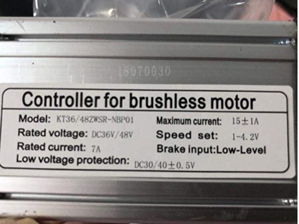
I’m looking for an e-bike controller (for 350W rear hub motor) that recognizes a rear dropout sensor with load cell (similar to TMM4) which has a variable output voltage from 0.52 to 4.4 volts (empirically measured with a voltmeter).
sensor.jpg

I saw in the forum that KT (Kunteng) controllers can be programmed for torque sensors using OSEC from GitHub.com.
Can anyone help me to know if:

1. Can KT controllers fit in my case?
2. Are there other controllers that can work?

Many thanks for your help :)

p.s. I have already excluded Greentech's Cycle Analist because it is too bulky for my bike ....
 
albe3 said:
p.s. I have already excluded Greentech's Cycle Analist because it is too bulky for my bike ....

That is the only one I know of in my limited user knowledge. If it s too bulky, you can run it de-cased and not use the display, just shove the circuit board into a compartment, tape it to the top of the controller, ect, just the pcb.

The only one I know of that can take that signal. and make usable. Just a suggestion. It does not have to live on the handlebar.
 
Almost every controller manufacturers are making controllers that can read a PAS signal. As long as it is within 0-5v you can make it work with any controller that can drive your motor, even those that are not programmable and/or read only throttle signal. I mean, if you can’t tune the controller response, you can alter the signal itself to feed the controller the signal range that it is set to exploit. Yet, if you want the rider to be able to program the controller response, or set assist levels on the fly, you will need a controller and display combo.

Nobody can tell if a controller will fit in your case, since we know nothing about you case and what you plan to put in it.
 
Many thanks DogDipstick
it is a nice idea to de-case the pcb of the CA,
I am not an electronics expert but I think I should first perform the various settings and then disassemble the pcb ...
in this way, however, I will have no display and, for example, I will not be able to select the assistance levels while driving.
It's right?
:wink:
 
Many thanks MadRhino
I'm not an electronics expert and I don't have an oscilloscope to check the waveform of the signal of the rear dropout sensor.
I tried a few pairs of cheap Chinese controller-displays with throttle input and cadence PAS input (disc with magnets), but none of them worked.
Unfortunately I don't know how to alter the sensor signal ...
I made the topic in the hope that someone had already successfully tested Kunteng controllers (or others) with this type of effort sensors ...
Thanks again :)
 
MadRhino said:
Almost every controller manufacturers are making controllers that can read a PAS signal. As long as it is within 0-5v you can make it work with any controller that can drive your motor, even those that are not programmable and/or read only throttle signal. I mean, if you can’t tune the controller response, you can alter the signal itself to feed the controller the signal range that it is set to exploit. Yet, if you want the rider to be able to program the controller response, or set assist levels on the fly, you will need a controller and display combo.

Nobody can tell if a controller will fit in your case, since we know nothing about you case and what you plan to put in it.

To clarify (allowing me to follow this) are we talking about a drop out mounted torque sensor, or are we talking about a simple cadence sensor? I get where about any controller will handle a simple cadence sensor input, but when you start talking torque sensor input things change a bit.
 
The controller doesn’t know what produced the signal, it only reads the signal that need to be within 0-5v and turns it into a speed control to the motor.

If you want the torque sensing signal to be effectively producing a power level output from the controller instead of speed, then you are limited to the few controllers that are ‘field oriented’ (FOC).
 
MadRhino said:
The controller doesn’t know what produced the signal, it only reads the signal that need to be within 0-5v and turns it into a speed control to the motor.

If you want the torque sensing signal to be effectively producing a power level output from the controller instead of speed, then you are limited to the few controllers that are ‘field oriented’ (FOC).

I think I follow that. You are saying that torque sensor output is similar to (or the same as?) the signal generated by a throttle? I get the operational voltage range piece, thinking more along the line of modulation or pulse width. Is there a difference there?

What would happen if I unplugged my throttle and plugged a torques sensor into that controller feed using a production bike type controller?

Not sure I understand the difference between something like a KT controller, and an "FOC" controller. Can you expend on that easily? Not looking for you to go to the trouble of a long explanation. If necessary, maybe just point me at something that might allow me to get the basic idea. Not interested in electrical engineering detail. That's just beyond me.
 
Yep. It is the same signal: variable voltage between 0 and 5v. The throttle input can be used, providing that you test and find the proper wiring to make it work.

FOC controllers (commonly field oriented or vector control) are feeding the motor a variation of the magnetic field by frequency control via nodulation. To make it simple: the motor always receive full speed voltage, only power varies with frequency modulation, making it torque control instead of speed control. The perceptible effect is like you twist the throttle full on a gasser, then control the speed with the clutch. :D

Of course it is not what happens with electricity, because there is no friction created. But, it is an example of the different approach and the resulted effect. FOC controllers are making the smoothest and most efficient operation.
 
MadRhino » Jun 23 2021 7:14pm

Yep. It is the same signal: variable voltage between 0 and 5v. The throttle input can be used, providing that you test and find the proper wiring to make it work.

I connected the rear dorpout sensor (see image already posted) in the throttle input of three different generic Chinese controllers. The connection is simple, there are only three cables (+, gnd and signal) but none of them worked.
The voltage supplied by the sensor is variable between 0 and 5 volts, but there is probably a waveform problem or something else I don't know ....
 
MadRhino said:
Yep. It is the same signal: variable voltage between 0 and 5v. The throttle input can be used, providing that you test and find the proper wiring to make it work.
....

I connected the rear dorpout sensor (see image already posted) in the throttle input of three different generic Chinese controllers. The connection is simple, there are only three cables (+, gnd and signal) but none of them worked.
The voltage supplied by the sensor is variable between 0 and 5 volts, but there is probably a waveform problem or something else I don't know ....
 
DogDipstick said:
...
That is the only one I know of in my limited user knowledge. If it s too bulky, you can run it de-cased and not use the display....

Many thanks DogDipstick
it is a nice idea to de-case the pcb of the CA,
I am not an electronics expert but I think I should first perform the various settings and then disassemble the pcb ...
in this way, however, I will have no display and, for example, I will not be able to select the assistance levels while driving.
It's right?
:wink:
 
MadRhino said:
Almost every controller manufacturers are making controllers that can read a PAS signal. As long as it is within 0-5v you can make it work with any controller that can drive your motor, even those that are not programmable and/or read only throttle signal. I mean, if you can’t tune the controller response, you can alter the signal itself to feed the controller the signal range that it is set to exploit. Yet, if you want the rider to be able to program the controller response, or set assist levels on the fly, you will need a controller and display combo.

Nobody can tell if a controller will fit in your case, since we know nothing about you case and what you plan to put in it.

Many thanks MadRhino
I'm not an electronics expert and I don't have an oscilloscope to check the waveform of the signal of the rear dropout sensor.
I tried a few pairs of cheap Chinese controller-displays with throttle input and cadence PAS input (disc with magnets), but none of them worked.
Unfortunately I don't know how to alter the sensor signal ...
I made the topic in the hope that someone had already successfully tested Kunteng controllers (or others) with this type of effort sensors ...
Thanks again :)
 
There are 2 different PAS signal forms: pulsed and continuous. If your PAS signal is pulsed (which normally is more common on cadence PAS), the signal will need to be transformed in order to supply the throttle control input. A small resistor and a capacitor would do, according to some who had done it before. That is by memory, from a thread that I read here on ES a few years ago.
 
MadRhino said:
There are 2 different PAS signal forms: pulsed and continuous. If your PAS signal is pulsed (which normally is more common on cadence PAS), the signal will need to be transformed in order to supply the throttle control input. A small resistor and a capacitor would do, according to some who had done it before. That is by memory, from a thread that I read here on ES a few years ago.

Hi MadRinho,
My PAS sensor is not of the cadence type, it records the strain produced by the chain by means of a load cell and transforms it into a signal ranging from 0 to 5 volts. But I don't know what characteristics this signal has ... :(
I think it is a continuous signal similar to that of throttles, but the controllers I tested do not recognize it ...
 
docw009 said:
You can buy a Juiced controller, as he uses that torque sensor part, but he charges $199USD, Surely you can buy a replacement for your bike from the manufacturer for equal money and have it fit exactky?

:thumb: :) :wink: Thanks docw009
 
Been following with interest as I believe a some what generic torque type sensor wired to a generic type controller would be a nice feature.


I would suspect that your controllers are expecting a hall sensored throttle's .8 to 3.6 vdc variable input at the controller's throttle input wire. The sticker on such a controller will verify this, as seen by the "speed set 1-4.2V" seen here...


UnqT5Mq.jpg


You mention both an out-put of .52 to 4.4vdc to start, then mention 0 to 5 vdc lately. :?:

A controller that is expecting a hall sensored throttle signal will certainly not respond to a starting input of 0vdc, as it would think that the throttle is broken and may set an error code.
For the same reason, a starting voltage of .52vdc may be under the threshold that the controller recognizes as a viable throttle input.

I would start by using a typical hall sensored throttle. To verify that your wiring is correct and the controller is functional and operates correctly with it.

If so, wire up your torque sensor after finding the torque input needed to obtain an output of .8 to under 1vdc output and hold it there. Power up your system, and making sure you don't let the output go below .8vdc. Vary the output voltage and see if it works.

If you are running in 0-5vdc output range, note that some controllers will also lock out with a signal of over ~ 4.6vdc. Thinking that the throttle has shorted...

Not to low on the start-up (controller powering up)... not to high at the end, or typical wide open throttle.

If you see some action :shock: perhaps we can come up with a modification that would keep your torque sensor's output in the ballpark. Hopefully the output is already modified to help eliminate hunting, and overshoot... but first things first.


Regards,
T.C.
 
Based on what I've seen to date, my take on the ability of a run of the mill/generic controller, is that they are NOT ABLE to correctly use a torque sensor. Period.

That said, if you're into electronics you may be able to cobble up a reasonable attempt at making one work using the controller throttle input - possibly putting the use of a stand alone throttle in question - without even more modifications.
 
TommyCat said:
Been following with interest as I believe a some what generic torque type sensor wired to a generic type controller would be a nice feature.
I would suspect that your controllers are expecting a hall sensored throttle's .8 to 3.6 vdc variable input at the controller's throttle input wire. The sticker on such a controller will verify this, as seen by the "speed set 1-4.2V" seen here...
...........

Regards,
T.C.

Thank you very much TommyCat,
Your information is very interesting.
I will do some tests to better modulate the signal voltage in the range you indicated.
Best Regards
:thumb: :D
 
TommyCat said:
Glad to help. :)

If you'd like more information on hall sensored throttles, their out-puts, as well as details on how to modify them... see this thread.
........

thanks again TommyCat
Best
:wink:
 
Back
Top