Please recommend proper grease for this

ebike11

1 MW
Joined
Nov 16, 2013
Messages
2,004
Location
far away
Hi guys
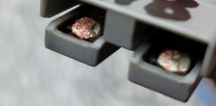
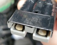
I just got my Anderson connectos and housings ready but didnt put any lubrication on the actual metal terminals
They spark every time i connect to my controller causing pitting and damage to them. Now they are almost impossible to connect together.
These are SB50A. Should i be putting conductive lubrication on these right from the start? Which type is recommend since i read the it should be conductive grease.
Thanks!
 

Attachments

  • 20220723_153449.jpg
    20220723_153449.jpg
    124.8 KB · Views: 1,593
  • 20220723_153517.jpg
    20220723_153517.jpg
    269.4 KB · Views: 1,593
Scrape the rough stuff off the tips. The tips are meant to be sacrificial. The real connections happens further up, at full engagement, after the tips have sparked.
 
You would use non-conductive dielectric grease to prevent corrosion and seal the connector. Putting a conductive substance on it would be a good way of creating a short.
 
No more spark. No problem add are incline pre-resistor. What voltage are you running ? I would replace connector or find a nail file yes a wooden one so you can cut to fit and when worn just cut back for new surface .
 
Gebus USE A PRECHARGE CIRCUIT !!!

Precharge is R*C=T


I use Penetrox conductive grease, specifically made for this. Penetrox makes a long line of conductive greases for copper/aluminum, copper / copper, or other exotic metal connections to enhance conductivity. Trusted for decades by electricians.

penetrox penetrox penetrox.
 
RunForTheHills said:
You would use non-conductive dielectric grease to prevent corrosion and seal the connector. Putting a conductive substance on it would be a good way of creating a short.

The plastic of the " anderson style" connector provides insulation from terminal to terminal. If you would meg it.

Use a conductive grease.. not a non conductive one. I have heard trouble conducting reports of people using dielectric grease here on Sur Ron batteries. Dielectric literally means " does not conduct".." insulating" . Penetrox specifically makes a few that are made for copper /copper conductors.


https://www.galco.com/shop/PENETROX-Burndy-Electrical-Joint-Compound-Chemicals

https://www.galco.com/buy/Burndy/PENE8

PENETROX Series Information

Excellent Oxide Inhibitor
Improves Electrical Conductivity
Non-Toxic
Doubles as a Thread Lubricant
Helps Prevent Seizing
Three Formulations Available
Seven Container Sizes
 
99t4 said:
Scrape the rough stuff off the tips. The tips are meant to be sacrificial. The real connections happens further up, at full engagement, after the tips have sparked.

But each time i connect, it sparks and causes the tips to become rough :(
 
999zip999 said:
No more spark. No problem add are incline pre-resistor. What voltage are you running ? I would replace connector or find a nail file yes a wooden one so you can cut to fit and when worn just cut back for new surface .

I am using 117V pack when fully charged...28s.
I think if i file the rough surface it will just happen again without a resistor. What resistor are you using?
 
DogDipstick said:
Gebus USE A PRECHARGE CIRCUIT !!!

Precharge is R*C=T


I use Penetrox conductive grease, specifically made for this. Penetrox makes a long line of conductive greases for copper/aluminum, copper / copper, or other exotic metal connections to enhance conductivity. Trusted for decades by electricians.

penetrox penetrox penetrox.

Yes looks like i will need a precharge resistor. It sparks every time i connect.
My max. voltage is 117 or so fully charged. Is there a resistor you can recommend? Thx!
 
No.

QS8 and QS10 are recommended for these installs all the time.. but.. they dont cut it. It is silly, I have burned out or eroded all the contacts with those premade 5.6 ohm resistances inside them.

A QS8, 10, or XT90-s are ALL 5.6 ohms precharge resistor of like 2w rating .. made to precharge rc hobby batteries on the esc... at 22v nomninal. Low voltage. Only.

You have 5 TIMES !! that.. .... " 22v". you need a MUCH slower precharge than a 5.6 ohm 2w would provide. RC has small caps and tiny esc made for 22.2v .. Lol... You have 117v... a big controller... with some very big ( capacitance) capacitors... Especially with 200v caps ( that your 117v controller almost certainty has, ie big spark) .

Do the math. You can see how much faster a 6 ohm is compared to say.. A 100 ohm 10w resistor. Or use a 1000 Ohm 10 watt resistor. If you dont know the math i will lay it out for you . You want a circuit to keep the high current form hitting the controller and blowing up caps or sparking contacts.

1KOhm, 10watt.

A QS8 or QS10 is a band aid and does not protect the controller well and is not good for a long life in a system.

Use Precharge relays.
 
DogDipstick said:
No.

QS8 and QS10 are recommended for these installs all the time.. but.. they dont cut it. It is silly, I have burned out or eroded all the contacts with those premade 5.6 ohm resistances inside them.

A QS8, 10, or XT90-s are ALL 5.6 ohms precharge resistor of like 2w rating .. made to precharge rc hobby batteries on the esc... at 22v nomninal. Low voltage. Only.

You have 5 TIMES !! that.. .... " 22v". you need a MUCH slower precharge than a 5.6 ohm 2w would provide. RC has small caps and tiny esc made for 22.2v .. Lol... You have 117v... a big controller... with some very big ( capacitance) capacitors... Especially with 200v caps ( that your 117v controller almost certainty has, ie big spark) .

Do the math. You can see how much faster a 6 ohm is compared to say.. A 100 ohm 10w resistor. Or use a 1000 Ohm 10 watt resistor. If you dont know the math i will lay it out for you . You want a circuit to keep the high current form hitting the controller and blowing up caps or sparking contacts.

1KOhm, 10watt.

A QS8 or QS10 is a band aid and does not protect the controller well and is not good for a long life in a system.

Use Precharge relays.

Couldnt you use a precharge resistor together with QS10s ? I think the QS10s might be better at handling higher current than my Andersons


Yes certainly.

A proper long lasting EV takes good consideration of its precharge system, for good measure and many reasons. There can be a impropper design, and a proper design, ....
So.
QS8 and QS10 are recommended for these installs all the time.. but.. they dont cut it. It is silly, I have burned out or eroded all the contacts with those premade 5.6 ohm resistances inside them.

H9owever, they are large current carrying connectors that can handle a good amount of load current when they are engaged properly.


A QS8, 10, or XT90-s are ALL 5.6 ohms precharge resistor of like 2w rating .. made to precharge rc hobby batteries on the esc... at 22v nomninal. Low voltage. Only.
You have 5 TIMES !! that.. .... " 22v". you need a MUCH slower precharge than a 5.6 ohm 2w would provide. RC has small caps and tiny esc made for 22.2v .. Lol... You have 120!!!!! v... a big controller... with some very big ( capacitance) capacitors... Especially with 200v caps ( that your 117v controller almost certainty has, ie big spark) .
Do the math. You can see how much faster a 6 ohm is compared to say.. A 100 ohm 10w resistor. Or use a 1000 Ohm 10 watt resistor. If you dont know the math i will lay it out for you . You want a circuit to keep the high current form hitting the controller and blowing up caps or sparking contacts.
1KOhm, 10watt. Good, slow precharge, not slamming the controller. Precharge takes 500 milliseconds.. current is limited, and the controller can do this 10,000 times without damage..
If you use a 5.6 ohm 2w.. you slam the controller with lots of current, erode contacts, and precharge in 10 milliseconds.. so t speak...

A QS8 or QS10 is a band aid and does not protect the controller well and is not good for a long life in a system.
Use Precharge relays. Thos big controller love to zap the 200v caps and that is a HUGE inrush of current.
If you dont want to wire a keyswitch to relays.. plus have a maintenance disconnect.. You are playing with " making sometihing work" as opposed to " a proper design... "

No real electric vehicle removes the battery at will. They are all bolted in and never disconnects physically from the car.. and the precharge is served by relays and keyswitches and fused circuitry.
Just run the battery current through a 1kohm 10w resistor to the controller right before you hook up main leads. I use a switched circuit for this. I hook up battery to a open system ( main switch open) .. engage precharge circuit... (10w1Kohm) .. wait a second.. and then throw the main switch contacts switchgear. This will completely get rid of the spark zap and give the controller a long healthy life with nothing getting hot.

Lets look at a correct.... 20w, 2000ohm precharge resistor ....vs the QS8 or QS10....
The math.

You are asking How much power will this 2K ohm 20watt take? When energized with a 117v circuit power source?
...under constant current conditions... at 117v... the 2000 ohm resistor conduct exactly 0.0585 amps current and will need to dissipate 6.84 watts (well within the 20w rating of the resistor)...

You will be fine with that. V=IR The 2K20w will only need to dissipate 6.8w of energy to be energized continuously. 6.8w on a 20w rated resistor is good continuous long lasting design, ie, reliable years down the line.

https://ohmslawcalculator.com/ohms-law-calculator

(Conversely.. Lets apply the same formula to a QS10... a QS10 of 5.6 ohms would need to dissipate 2444.46 watts and a current of 20A would travel through that resistance... and probably fry ( burn out?) the QS10 because it has a 2w resistor inside it.... and then you would be just " imagining" you are precharging.. because the user does not know any better but at least you got a cool black plug with a red line on it like all the cool kids) ...


If you dont have a " main disconnect switch"... and you " want to hook up the battery leads by hand.. " .. I will tell you automation is foolproof and this is why they dont do that in real electric cars.
(Human) Hands and voltage dont go together well.. ( see wiki on " electric chair") ... AND SO THERE FOR DESIGNERS TRY TO DESIGN WITH LITTLE "HUMAN " INTERACTION AS POSSIBLE WHEN THERE ARE ISOLATED SYSTEMS AT PLAY AND HIGH VOLTAGES ( THAT 120V CERTAINLY IS ) ... >>>>

So.. either you can be the " Switch" for the rest of you life ( dangerous) or you can buy a proper relay solenoid switch. I am not one to say which you will do, you will do what you want.. but.. be careful with 120v DC and a strong battery. I would rather keep all " hands" and " plugging in " out of the plan if I were you.
It is a concept of " idiotproofing"... The lesser human interaction, the less there is to go wrong.

Also to make not of.. ONCE the main contacts are connected.. ALL power stops flowing through the prechage circuits. All current stops through this part of the circuit ( the 6.8w, ) because it has a new, lower resistance path to follow.. ( the main leads)...
this is why some get away with a QS10... they plug it in fast.. to not burn out the resistor.. But this negates the precharge function of the s resistance..

.... but every now and again.. you see someone who was recommend the QS10 or XT90s or QS8.. and they plugged it in.. but not all the way.. and the next thing they know they have a burning, smoking mess on the lines cause the current is burning up the 5.6OHM 2W resistance of the QS8.... 20A and 2000w is just turning that thing to smoke, they panic, and rip the connectors apart. ..this is what happens if you mess up pluggin a 5.6 oHm QS10 into a circuit a little bit but not all the way.. Instant magic smoke.

You need the precharge female on the battery and the precharge male on the controller...
You think of the controller as a " basin of ducklings"... and the battery as a " lake of water"... You want to fill the basin slowly.. with a trickle ( first... ) .. with the precharge resistor... Then apply full battery voltage to the controller ( second)..

If you fill the basin with a 5 gallon bucket thown at the ducks ( 5.6oHm resistor, qs10?) the ducklings get mad.
If you fill the basin with a fire hose the ducklings get even madder ( and maybe even injured)... ( no precharge at all) .
The 20w2K resistor is a good " trickle". Will not hurt the duckies. Will fill the basin so that you can then they can get out to the lake and play.

Nothing wrong with a good manual precharge system. Just becomes a burden to remember every time but i do it that way. It will protect the controller well and keep your contacts from arc flashing.
120vDC is not something you want to play with to much by hand. Andersons have very good insulation and you will not have to touch anything hot. you could use a 20g wire for this, easily, it takes less than an amp when energized. That will fill the basin slowly, THEN connect the main contacts, and that is the good way to do it.

A spade terminal. A banana plug like from a multimeter. a small rc grade gold banana. it only needs to take 1 amp with a 2K resistance. Its half an amp of current and very low dissipate power.
Precharge does not take alot of " energy".. it only takes a finite, small, amount. To keep the shock wave of the battery connection fro filling the controller electronics and causing damage to fast. Once charged, the current drops to 0 in that line. However, a good precharge saves electronics form damage from " inrush current".
 
DogDipstick said:


Yes certainly.

A proper long lasting EV takes good consideration of its precharge system, for good measure and many reasons. There can be a impropper design, and a proper design, ....
So.
QS8 and QS10 are recommended for these installs all the time.. but.. they dont cut it. It is silly, I have burned out or eroded all the contacts with those premade 5.6 ohm resistances inside them.

H9owever, they are large current carrying connectors that can handle a good amount of load current when they are engaged properly.


A QS8, 10, or XT90-s are ALL 5.6 ohms precharge resistor of like 2w rating .. made to precharge rc hobby batteries on the esc... at 22v nomninal. Low voltage. Only.
You have 5 TIMES !! that.. .... " 22v". you need a MUCH slower precharge than a 5.6 ohm 2w would provide. RC has small caps and tiny esc made for 22.2v .. Lol... You have 120!!!!! v... a big controller... with some very big ( capacitance) capacitors... Especially with 200v caps ( that your 117v controller almost certainty has, ie big spark) .
Do the math. You can see how much faster a 6 ohm is compared to say.. A 100 ohm 10w resistor. Or use a 1000 Ohm 10 watt resistor. If you dont know the math i will lay it out for you . You want a circuit to keep the high current form hitting the controller and blowing up caps or sparking contacts.
1KOhm, 10watt. Good, slow precharge, not slamming the controller. Precharge takes 500 milliseconds.. current is limited, and the controller can do this 10,000 times without damage..
If you use a 5.6 ohm 2w.. you slam the controller with lots of current, erode contacts, and precharge in 10 milliseconds.. so t speak...

A QS8 or QS10 is a band aid and does not protect the controller well and is not good for a long life in a system.
Use Precharge relays. Thos big controller love to zap the 200v caps and that is a HUGE inrush of current.
If you dont want to wire a keyswitch to relays.. plus have a maintenance disconnect.. You are playing with " making sometihing work" as opposed to " a proper design... "

No real electric vehicle removes the battery at will. They are all bolted in and never disconnects physically from the car.. and the precharge is served by relays and keyswitches and fused circuitry.
Just run the battery current through a 1kohm 10w resistor to the controller right before you hook up main leads. I use a switched circuit for this. I hook up battery to a open system ( main switch open) .. engage precharge circuit... (10w1Kohm) .. wait a second.. and then throw the main switch contacts switchgear. This will completely get rid of the spark zap and give the controller a long healthy life with nothing getting hot.

Lets look at a correct.... 20w, 2000ohm precharge resistor ....vs the QS8 or QS10....
The math.

You are asking How much power will this 2K ohm 20watt take? When energized with a 117v circuit power source?
...under constant current conditions... at 117v... the 2000 ohm resistor conduct exactly 0.0585 amps current and will need to dissipate 6.84 watts (well within the 20w rating of the resistor)...

You will be fine with that. V=IR The 2K20w will only need to dissipate 6.8w of energy to be energized continuously. 6.8w on a 20w rated resistor is good continuous long lasting design, ie, reliable years down the line.

https://ohmslawcalculator.com/ohms-law-calculator

(Conversely.. Lets apply the same formula to a QS10... a QS10 of 5.6 ohms would need to dissipate 2444.46 watts and a current of 20A would travel through that resistance... and probably fry ( burn out?) the QS10 because it has a 2w resistor inside it.... and then you would be just " imagining" you are precharging.. because the user does not know any better but at least you got a cool black plug with a red line on it like all the cool kids) ...


If you dont have a " main disconnect switch"... and you " want to hook up the battery leads by hand.. " .. I will tell you automation is foolproof and this is why they dont do that in real electric cars.
(Human) Hands and voltage dont go together well.. ( see wiki on " electric chair") ... AND SO THERE FOR DESIGNERS TRY TO DESIGN WITH LITTLE "HUMAN " INTERACTION AS POSSIBLE WHEN THERE ARE ISOLATED SYSTEMS AT PLAY AND HIGH VOLTAGES ( THAT 120V CERTAINLY IS ) ... >>>>

So.. either you can be the " Switch" for the rest of you life ( dangerous) or you can buy a proper relay solenoid switch. I am not one to say which you will do, you will do what you want.. but.. be careful with 120v DC and a strong battery. I would rather keep all " hands" and " plugging in " out of the plan if I were you.
It is a concept of " idiotproofing"... The lesser human interaction, the less there is to go wrong.

Also to make not of.. ONCE the main contacts are connected.. ALL power stops flowing through the prechage circuits. All current stops through this part of the circuit ( the 6.8w, ) because it has a new, lower resistance path to follow.. ( the main leads)...
this is why some get away with a QS10... they plug it in fast.. to not burn out the resistor.. But this negates the precharge function of the s resistance..

.... but every now and again.. you see someone who was recommend the QS10 or XT90s or QS8.. and they plugged it in.. but not all the way.. and the next thing they know they have a burning, smoking mess on the lines cause the current is burning up the 5.6OHM 2W resistance of the QS8.... 20A and 2000w is just turning that thing to smoke, they panic, and rip the connectors apart. ..this is what happens if you mess up pluggin a 5.6 oHm QS10 into a circuit a little bit but not all the way.. Instant magic smoke.

You need the precharge female on the battery and the precharge male on the controller...
You think of the controller as a " basin of ducklings"... and the battery as a " lake of water"... You want to fill the basin slowly.. with a trickle ( first... ) .. with the precharge resistor... Then apply full battery voltage to the controller ( second)..

If you fill the basin with a 5 gallon bucket thown at the ducks ( 5.6oHm resistor, qs10?) the ducklings get mad.
If you fill the basin with a fire hose the ducklings get even madder ( and maybe even injured)... ( no precharge at all) .
The 20w2K resistor is a good " trickle". Will not hurt the duckies. Will fill the basin so that you can then they can get out to the lake and play.

Nothing wrong with a good manual precharge system. Just becomes a burden to remember every time but i do it that way. It will protect the controller well and keep your contacts from arc flashing.
120vDC is not something you want to play with to much by hand. Andersons have very good insulation and you will not have to touch anything hot. you could use a 20g wire for this, easily, it takes less than an amp when energized. That will fill the basin slowly, THEN connect the main contacts, and that is the good way to do it.

A spade terminal. A banana plug like from a multimeter. a small rc grade gold banana. it only needs to take 1 amp with a 2K resistance. Its half an amp of current and very low dissipate power.
Precharge does not take alot of " energy".. it only takes a finite, small, amount. To keep the shock wave of the battery connection fro filling the controller electronics and causing damage to fast. Once charged, the current drops to 0 in that line. However, a good precharge saves electronics form damage from " inrush current".

Thank you for your great information...some of it is over my head but ill read it carefully.

So if i have a 20w 2k resistor wired to the positive leads of my battery with roughly 120V full charge, how long would i need to wait after plugging in the preresistor connector first before connecting my main power leads? Thanks!!
 
I sorry you forgot to answer the voltage oh yes very important. Ok.


No more spark. No problem add are incline pre-resistor. What voltage are you running ? I would replace connector or find a nail file yes a wooden one so you can cut to fit and when worn just cut back for new surface .
So what voltage you running ???
 
ebike11 said:
Thank you for your great information...some of it is over my head but ill read it carefully.

So if i have a 20w 2k resistor wired to the positive leads of my battery with roughly 120V full charge, how long would i need to wait after plugging in the preresistor connector first before connecting my main power leads? Thanks!!

To tell you that, I would need to know the capacitance of your controller. Different controller have different capacitors.. and.. this will make the inrush time different between them.

T= R * C

Off the top of my head?no info of the controller? Knowing typical ebike controllers? Like a second or two. Fast.


The resistance of the precharge resistor is chosen based on the capacity of the load and the desired precharge time. The precharge surge current reaches 1/e of its initial value after a time of:
T = R * C
The current is reduced to a manageable value after approximately a time of 5 * T.
So, if the desired precharge time is 500 ms, and the load capacity is 10,000 µF, then:
R = T / C / 5 = 500 ms / 10,000 µF / 5 = 10 Ohm

The precharge resistor needs to dissipate as much energy as the energy stored in the load's input capacitors. So, for example, with a 100 V battery voltage and a 10,000 µF capacitance, the energy in the charged capacitors (and therefore the energy dissipated by the precharge resistor during turn on) is:
E = (C * V^2) / 2 = (10,000 µF * 100 V^2) / 2 = 50 Joules.
The power dissipated by the precharge resistor during precharge is that energy over the precharge time. For example, with a precharge time of 500 ms:
P = E / T = 50 J / 500 ms = 100 W

At the very beginning of the precharge, the instantaneous power will be quite high:
P = V^2 / R = 100 ^2 / 10 = 1000 W!

Now, over the long term, the precharge resistor will not need to dissipate any significant power (it will not get hot). But, during the precharge, the precharge resistor will be stressed by that high, sudden power. That is why the precharge resistor needs to be very sturdy and high power, yet it doesn't need a heat sink.

Some manufacturers specify the peak power dissipation. For example: "Overload: 5 times rated wattage for 5 seconds.".
In that case, a 50 W resistor will be handle 500 W (well above the 100 W of the example above).
Ultimately, you should ask the resistor manufacturer if a particular resistor will work in your application, and try the resistor in the application.

Quote from : http://liionbms.com/php/precharge.php
 
I was working on this last night,

Most of my low power bikes have:

Controller > XT60 male

Battery > XT 60 female

I will use this controller > inrush plug > battery

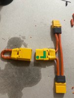
to charge the controller and use xt90 as a plug/switch too. I saw this solution here/youtube
 

Attachments

  • inrush_xt90.jpg
    inrush_xt90.jpg
    170 KB · Views: 1,405
I think that is called a " Loop Key"... Yup! Great idea.
 
DogDipstick said:
ebike11 said:
Thank you for your great information...some of it is over my head but ill read it carefully.

So if i have a 20w 2k resistor wired to the positive leads of my battery with roughly 120V full charge, how long would i need to wait after plugging in the preresistor connector first before connecting my main power leads? Thanks!!

To tell you that, I would need to know the capacitance of your controller. Different controller have different capacitors.. and.. this will make the inrush time different between them.

T= R * C

Off the top of my head?no info of the controller? Knowing typical ebike controllers? Like a second or two. Fast.


The resistance of the precharge resistor is chosen based on the capacity of the load and the desired precharge time. The precharge surge current reaches 1/e of its initial value after a time of:
T = R * C
The current is reduced to a manageable value after approximately a time of 5 * T.
So, if the desired precharge time is 500 ms, and the load capacity is 10,000 µF, then:
R = T / C / 5 = 500 ms / 10,000 µF / 5 = 10 Ohm

The precharge resistor needs to dissipate as much energy as the energy stored in the load's input capacitors. So, for example, with a 100 V battery voltage and a 10,000 µF capacitance, the energy in the charged capacitors (and therefore the energy dissipated by the precharge resistor during turn on) is:
E = (C * V^2) / 2 = (10,000 µF * 100 V^2) / 2 = 50 Joules.
The power dissipated by the precharge resistor during precharge is that energy over the precharge time. For example, with a precharge time of 500 ms:
P = E / T = 50 J / 500 ms = 100 W

At the very beginning of the precharge, the instantaneous power will be quite high:
P = V^2 / R = 100 ^2 / 10 = 1000 W!

Now, over the long term, the precharge resistor will not need to dissipate any significant power (it will not get hot). But, during the precharge, the precharge resistor will be stressed by that high, sudden power. That is why the precharge resistor needs to be very sturdy and high power, yet it doesn't need a heat sink.

Some manufacturers specify the peak power dissipation. For example: "Overload: 5 times rated wattage for 5 seconds.".
In that case, a 50 W resistor will be handle 500 W (well above the 100 W of the example above).
Ultimately, you should ask the resistor manufacturer if a particular resistor will work in your application, and try the resistor in the application.

Quote from : http://liionbms.com/php/precharge.php

Do i need to wire the resistor a certain way? One end facing the controller and the other towards the battery? Or does it matter.
There was no markings on my resistor besides the 20w 2k
 
gobi said:
I was working on this last night,

Most of my low power bikes have:

Controller > XT60 male

Battery > XT 60 female

I will use this controller > inrush plug > battery

to charge the controller and use xt90 as a plug/switch too. I saw this solution here/youtube

So did you add a resistor or maybe the XT 90 is the resistor? I’m learning from this thread too 8)
 
Eastwood said:
gobi said:
I was working on this last night,

Most of my low power bikes have:

Controller > XT60 male

Battery > XT 60 female

I will use this controller > inrush plug > battery

to charge the controller and use xt90 as a plug/switch too. I saw this solution here/youtube

So did you add a resistor or maybe the XT 90 is the resistor? I’m learning from this thread too 8)

The xt 90 has the green lined connection, this connector has 2 parts:

The TIP (a few mils) is isolated from the bottom and this tip has an inline resistor.

So you barely touch the connector and hold it in that position for a 10 seconds for the caps to charge and then fully seat the connector,

I bought the AMass brand off amazon, they have a 4 or 6 pack and it is comes to a few bucks a connector!

I will post my item link later.
 
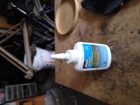
I was going to use Noalox for a battery build is it good for this ?
Here's pic of my pre resistor. For 72v.

16595681988447064489598988395158.jpg
Charging my battery and the xt60 was hot and I flared the the pins and the high heat went away. But was at end of charge. So must watch it. I don't like them or xt90 resistor on my mains . Not for 72v. To fragile
 
Ok use the Noalox on the plug for my 3 meanwells and it didn't pop as 1 sec earlier. So put it on my 60xt and no pop. Now going to grease up the 5.5mm to xt90s connectors
Yes noalox crazy1659650612823601441641949871306.jpg
Ok plugged the 3 meanwells into the wall again and a little pop. I read up on it and it is conducted Oh no magic
 
999zip999 said:
I was going to use Noalox for a battery build is it good for this ?
Here's pic of my pre resistor. For 72v.

16595681988447064489598988395158.jpg
Charging my battery and the xt60 was hot and I flared the the pins and the high heat went away. But was at end of charge. So must watch it. I don't like them or xt90 resistor on my mains . Not for 72v. To fragile


Hi...are you using 2 preresistors? I thought you only need 1 on the Positive leads?
 
Back
Top