Torque-Sensor Motor w/ Sine-Wave Controller Build

WhatcomRider

100 W
Joined
Apr 7, 2012
Messages
117
Location
Bellingham WA - USA
After reading up on the advantages of sine-wave controllers I was curious if any Chinese vendors are currently supplying them. A search on AliExpress turned up store no. 323339 (http://www.aliexpress.com/store/323339) that lists 12 e-bike conversion kits - some with integrated torque-sensor motors and/or sine-wave controllers - all designed for the European market. I was intrigued, so I initiated what turned out to be a lengthy email exchange with the store manager Yonggang Lu of Suzhou Minshine Electronics Co. I was interested in the 36V kit with all the goodies @ USD305. I asked for a higher speed motor to reach 18-20 mph and he was willing to part with a 280 rpm wind (e.q. 310 no-load rpm). I kept negotiating shipping costs down until Yonggang found a shipping company called JCEX that would ship the kit (less wheel) to the USA for USD98. Turned out that as a resident of WA state I couldn't purchase the kit through AliExpress due to some ongoing litigation with the state. I wasn't about to wire the money without some kind of protection, so Yonggang finally offered to ship the kit risk-free and I couldn't refuse.

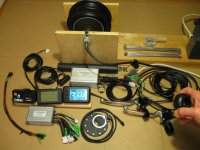
Last week the kit was shipped in the wee hours of Wednesday morning and arrived at my doorstep on Friday afternoon, a total of 2 1/2 days! Turned out JCEX handed the package over to Fedex Express in China upon which it was flown directly to Seattle and then loaded onto a Fedex truck heading north. The components were packed securely so that nothing was damaged. This is what I received (click to enlarge):

View attachment 1
Yonggang supplied the samples shown in the lower left - 2 different display units and a regular controller.

I have the kit hooked up on my kitchen table test bench, powered by my Ultramotor Europa 36V battery, and undergoing initial testing:
minshinekit2.jpg
Here you see that the motor has reached a no-load speed of 23.9 mph which by my calculations (23.9 * 336 / 26) equals 309 rpm, just what I ordered. I really like the LCD display - it is perfectly crisp and clear with a nice backlight (much better that what the photo shows) and well laid out.

The two sets of 18 spokes supplied with the kit are approx. 202mm and 208mm long, so I had to scratch my head a bit and head over to Edd (http://lenni.info/edd/) to figure out how I was going to build my wheel. Turned out that I had to do a 0 cross on the freewheel side and a 1 cross on the other side. A bit odd but seems strong enough.

Then I discovered that the dropout spacing was 130mm instead of 135mm. I will show you what I did in my next post.
 
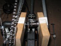
I needed to expand the dropout width on my cromoly mountain bike frame by 5mm so I came up with this:

dropoutexpansion1.jpg
I had to force the dropout distance to 160mm in order to get it to relax back to 135mm. As you see I am using a miniature jack screw with wooden blocks that I had on hand from a former profession. Any guesses as to what that was?
 
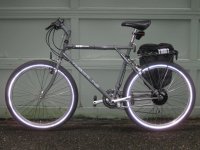
I installed the kit onto my 22 year-old GT Timberline 21-speed mountain bike in a temporary fashion.

minshinekit3.jpg
The battery is on loan from my Europa until I get something different. The controller and wiring I plan to hide underneath the rack in a custom box or wiring channel of some sort. The Big Apple tires are slated for an upcoming cargo bike build and will be replaced with Kenda Kwick Tendril commuting tires.

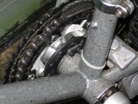
Actually the bike is now a 14-speed because I had to remove the inner chainring in order to fit the PAS disk.

minshinekit4.jpg
How does it ride? Well, first of all I must say that it is nice and quiet. When I am using pedal/torque assist I can feel, but barely hear, the power come on and can reach 22 mph with some effort. On throttle power alone I can hit 18 mph on the flats and 12 mph up a 5% grade. At all times the application of power is smooth with no stuttering of any kind.

I did encounter a minor problem with the motor build quality which I will show you next.
 
Here is my first ever YouTube vid which I recorded with my Canon PowerShot A590.

[youtube]1bdwfu56_ek[/youtube]

The motor noise is greatly exaggerated due to the close mic placement and very low ambient noise in the room (and I apologize for the annoying static from the camera mic). As you can see the hub wobbles from side to side a bit. I attribute that to the axle being off-center to the hub. Is this something I should be concerned about? Could it cause the motor to wear out faster?

The sine-wave controller is rated at 10-20 amps and is running in sensored mode. It is able to hold a steady speed as low as 3 rpm and smoothly ramps up to no-load speed. It is interesting that there is an audible change at around 130 rpm where it seems that the commutation shifts into a different mode.
 
Meltdown :(

So far I have put 130 miles on the bike with no problems, but the other day the motor failed at the top of the hill on my way home. When I opened up the motor I could tell from the eye-burning, acrid fumes that the windings had overheated. Then I noticed that what I assume to be nylon cords had melted at the outer edges of the windings. I am pretty sure the Hall sensors got fried to death - the melting temperature of nylon-6 is 220 degrees C - ouch! The 600 feet of elevation gain in 2 miles with most of the gain in the last 1/2 mile is apparently too much for this motor. In hindsight I estimate that the motor at times was running with full amps at about 40% of no-load speed. I should have known that the heat buildup would kill it. Live and learn, LOL.

I have decided to replace the motor with a slower wind version to hopefully avoid another meltdown. I will be ordering a 225 rpm no-load speed motor and new controller for half price from the seller. He will also send some replacement Hall sensors which might enable me to get the fried motor working again. Oil cooling might be an option, but that would be another project for another day.

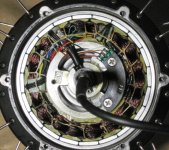
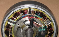
I uploaded several pics of the motor since some of you may be interested to see how the built-in torque sensor works. The motor is a rebranded XOFO produced by the Suzhou Xiongfeng Motor Co (http://www.szxfmotor.com/en/index.asp) which offers a line of motors similar to the Bafangs.

Upon first opening the motor and getting the whiff of disaster:

IMG_0416.JPG

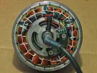
Rotor and stator removed from the hub:

View attachment 7

The melted cords and locaton of the 3 Hall sensor transistors:

IMG_0411.JPG

Black semi-circular piece holds 2 Hall sensors to detect the phase of the torque sensor magnets:

View attachment 5

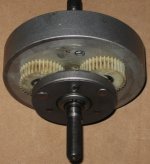
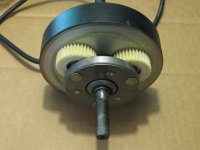
Rotor with freewheel clutch and nylon planetary gears:

IMG_0408.JPG

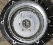
The ring gear and shaft bearing:

IMG_0404.JPG

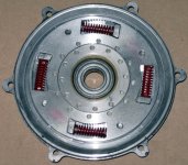
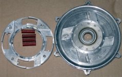
The 2 aluminum disks, 24 magnets, and 4 springs that make up the torque sensor:

IMG_0406.JPG

The outer disk of the torque sensor removed:

IMG_0407.JPG

So how does the torque sensor work? The freewheel is attached to the inner disk, so applying force to the pedals causes the inner disk to rotate against the four springs which changes the alignment of the two circular rows of magnets. The two Hall sensors send the magnet position signals to the controller which intreprets the phase difference between the signals as being proportional to the amount of torque applied through the pedals. The torque sensor signal is also sent via the controller to the display to calculate the speed of the bike.

edit by spinningmagnets: more pics of the interior parts of the XOFO found here: http://cyclurba.fr/forum/314672/mot...4564&messageID=350350&rubriqueID=89&pageprec=
 
Any update on this? Ingenious torque sensor design, but how does it report it to the controller? Otherwise this looks very similar to the Bafang SWXH . Is the controller and display available separately from the motor? Also, why if it is FOC does it even need Hall sensors?
 
-dg said:
Any update on this? Ingenious torque sensor design, but how does it report it to the controller? Otherwise this looks very similar to the Bafang SWXH . Is the controller and display available separately from the motor? Also, why if it is FOC does it even need Hall sensors?

The replacement motor turned out to have been damaged in shipping which resulted in an intermittent short in the cable where it exits the axle. I sent the damaged motor and controller back to the vendor and am expecting a new motor and controller any day now.

In addition to the 3 Hall signals from the stator, the motor sends 2 signals from the torque sensor to the controller. These 2 signals are out of phase with each other and the amount of phase difference indicates the amount of spring compression which is directly proportional to the amount of torque being transmitted to the freewheel.

The motor is made by XOFO which carries a line of motors very similar to the Bafangs. In fact, some of the parts (gears at least) are interchangeable. Yonggang Lu has worked for both companies so knows these motors well and can source whatever you need.

Yes, the controller and display are available separately from the motor. The sinus controllers are available in 6, 9, or 12 FET versions. You can get the wiring customized for your particular motor.

Hall sensors are required for smooth starts regardless of the commutation method. These controllers can also run in sensorless mode through software simulation of the Hall signals.
 
WhatcomRider said:
The replacement motor turned out to have been damaged in shipping which resulted in an intermittent short in the cable where it exits the axle. I sent the damaged motor and controller back to the vendor and am expecting a new motor and controller any day now.
...
Yes, the controller and display are available separately from the motor. The sinus controllers are available in 6, 9, or 12 FET versions. You can get the wiring customized for your particular motor.

Hall sensors are required for smooth starts regardless of the commutation method. These controllers can also run in sensorless mode through software simulation of the Hall signals.
Too bad about the delay, I hope it comes back together for you soon.

I would like to try a 6 or 9 fet controller, but I prefer sensorless operation at least as an option. I'm ok if the startup is a little rough as I push off first anyway before applying throttle. If their startup is similar to the KU63 it will be more than fine.

Anyway, I have a couple bikes to test controllers on, one with a Bafang BPM running 48 volts, I'd like 25 amps if possible. The other is a Bafang SWXK running 48 volts and currently 20 amps. Is there documentation or spec sheets for these controller? How would I go about ordering?

Thanks!
 
Getting a 48V controller at 25 amps is definitely possible. Here is the documentation I have on the controllers: View attachment Controller.EN.pdf
I think the ratings are conservative. My 6 FET controller rated at 10/20 amps puts out a decent amount of power. I will know more when I hook up my CA V3 (w/ shunt) to the controller to measure the current input under various loads. I will post the results here. Very clear and detailed wiring diagrams are also available.

To order, send an email to Yonggang Lu - yonggang.lu@minshine.cn - with your requirements. He will provide documentation and price quotes. He accepts payments via wire transfer or AliExpress (AliPay). It costs me $10 to do a wire transfer through my bank but there are no other transaction fees.
 
I've just noticed this thread. If these things can be made reliable, they could be a great solution for people looking for a "true assist" setup.

Looking at the photos of the damaged motor, it looks like the gears are showing wear already. Is it just my eyes, or is there an issue there?

Can you adjust the torque multiplication on the fly or is it fixed somewhere?
 
Ben Wilson said:
I've just noticed this thread. If these things can be made reliable, they could be a great solution for people looking for a "true assist" setup.

Looking at the photos of the damaged motor, it looks like the gears are showing wear already. Is it just my eyes, or is there an issue there?

Can you adjust the torque multiplication on the fly or is it fixed somewhere?
Hi Ben,

I agree that this system could be a great solution for a "true assist" setup (depending on one's definition :)). I intend to put some serious mileage on the bike this summer to find out how reliable it is.

I will open the new motor and compare its gears with the old one to make sure, but I think the gears are purposely made with a bit of concavity on teeth for the purpose of reducing noise. Perhaps that is what you are seeing as wear.

Yes, you can adjust the torque multiplication on the fly by setting levels 1 to 5 while pedaling. I find that level 5 is more that adequate and that I need to reduce the level to 1 if I am riding on a trail with tight turns. Most of the time I ride at level 3 or 4. Level 0 is human power only and level 6 is throttle mode only which is useful for stationary testing of the motor.

Robert
 
A package from Minshine arrived yesterday containing a new motor, two sine-wave controllers (one is a spare), and an e-bike tester. (The latter item I bought from cellman who sent it to Minshine so that I could save on shipping charges.)

The new motor with its shiny copper windings:

IMG_0440 (1024x768).jpg
The teeth of the planet gears are indeed concave across the outer edge:

IMG_0439 (1024x768).jpg

The bike is now back together and I took it for a test ride today - so far so good.

@ -dg, the CA test showed that the 36V 6 FET controller draws 14 amps from the battery at full power.
 
Good to hear about the gears. I was thinking about this motor the other day; with the torque sensor hooked up after the gears, wouldn't you get a different reading depending on what gear you are in? Is this something you notice when you are riding?
 
Ben Wilson said:
Good to hear about the gears. I was thinking about this motor the other day; with the torque sensor hooked up after the gears, wouldn't you get a different reading depending on what gear you are in? Is this something you notice when you are riding?
Good catch! It is true that the amount of torque applied to the sensor depends on the gear ratio, but the difference is subtle and is barely noticeable when riding. In practice, I find that I start in a higher (harder) gear than I would without assist, otherwise I wouldn't be able to change gears fast enough to keep a comfortable cadence.
 
WhatcomRider said:
-dg said:
Any update on this? Ingenious torque sensor design, but how does it report it to the controller? Otherwise this looks very similar to the Bafang SWXH . Is the controller and display available separately from the motor? Also, why if it is FOC does it even need Hall sensors?

The replacement motor turned out to have been damaged in shipping which resulted in an intermittent short in the cable where it exits the axle. I sent the damaged motor and controller back to the vendor and am expecting a new motor and controller any day now.

In addition to the 3 Hall signals from the stator, the motor sends 2 signals from the torque sensor to the controller. These 2 signals are out of phase with each other and the amount of phase difference indicates the amount of spring compression which is directly proportional to the amount of torque being transmitted to the freewheel.

The motor is made by XOFO which carries a line of motors very similar to the Bafangs. In fact, some of the parts (gears at least) are interchangeable. Yonggang Lu has worked for both companies so knows these motors well and can source whatever you need.

Yes, the controller and display are available separately from the motor. The sinus controllers are available in 6, 9, or 12 FET versions. You can get the wiring customized for your particular motor.

Hall sensors are required for smooth starts regardless of the commutation method. These controllers can also run in sensorless mode through software simulation of the Hall signals.

Is there anyway we can prove that these controllers are actually sinewave?
 
Nanoha said:
...
Is there anyway we can prove that these controllers are actually sinewave?
You inspired me to hook up an oscilloscope to the controller in order to view the output waveforms.

Here is the waveform between a pair of phase leads:

[youtube]K9EG2Y_Fu1U[/youtube]

Here is the waveform between ground and a phase lead:

[youtube]3H6ZJMy8BiQ[/youtube]

The ground-to-phase waveform shows that the controller is using space-vector modulation which results in 15% better utilization of the DC bus voltage over the simplest form of sine wave modulation. I don't fully understand how SVM works, but there is a partial explanation on this page: http://robotics.stackexchange.com/questions/261/what-do-the-commutation-waveforms-look-like-for-a-brushless-motor.
 
Any update on the replacement motor?
I'm converting a mid 80's pinarello steel road bike and want torque sensing for throttle as I have drop and aero bars.
I normally ride 18 to 20 mph pedal only on the flats on half of my 15 mile commute, the other half (where I want the assist) is up to 6% grades.
It seems like 36V, 10aHr LiPo would do it, I would prefer a rear wheel drive,geared motor.
Does the sine wave controller increase efficiency/range?
 
roadbiker said:
Any update on the replacement motor?
I'm converting a mid 80's pinarello steel road bike and want torque sensing for throttle as I have drop and aero bars.
I normally ride 18 to 20 mph pedal only on the flats on half of my 15 mile commute, the other half (where I want the assist) is up to 6% grades.
It seems like 36V, 10aHr LiPo would do it, I would prefer a rear wheel drive,geared motor.
Does the sine wave controller increase efficiency/range?
The new replacement motor is working fine. By using a lower level of assist (3 instead of 5) on the same hills that fried the first motor, I notice that the new motor barely gets warm. So that's a relief. And by pedaling a bit harder I can still maintain 8-10 mph on the steepest ones. Also, there is very little wobble in this motor compared to the first one.

In theory there may be some efficiency gain with a sine wave controller, but in practice it is probably on par with a six step square wave controller. I think that the quality of the MOSFETS would be more significant.

Setting a low level of assist will give you good range, but I can't say what it would be because there are so many factors to consider.

I think a Minshine kit would work well for your purposes.
 
It is interesting that there is an audible change at around 130 rpm where it seems that the commutation shifts into a different mode.

Do you still get that audible change in the new motor roughly at the same RPM?
 
4REEE said:
It is interesting that there is an audible change at around 130 rpm where it seems that the commutation shifts into a different mode.

Do you still get that audible change in the new motor roughly at the same RPM?
Yes, and I verified with the scope that the output waveform becomes a cleaner looking sine wave at that RPM. But if I slow the motor and speed it up again the audible change occurs at around 90 RPM. When I am riding the bike I don't notice the audible changes. I am at a loss to explain what is going on here.
 
I am at a loss to explain what is going on here.

I can't find the article, but I seem to remember reading that at certain RPMs, there is what's called a "bell" noise. I think that at a certain RPM, a resonant frequency gets hit and the it's the motor housing that's responding to that resonant frequency.
 
4REEE said:
I can't find the article, but I seem to remember reading that at certain RPMs, there is what's called a "bell" noise. I think that at a certain RPM, a resonant frequency gets hit and the it's the motor housing that's responding to that resonant frequency.
This reminds me of something (just for fun):

[youtube]7BQ9lei_24Y[/youtube]

Can you imagine doing this with a big DD hub motor? What a trip that would be.

Tremendous resource for learning about and building sine wave controllers: Shane Colton.
 
WhatcomRider said:
4REEE said:
I can't find the article, but I seem to remember reading that at certain RPMs, there is what's called a "bell" noise. I think that at a certain RPM, a resonant frequency gets hit and the it's the motor housing that's responding to that resonant frequency.
This reminds me of something (just for fun):

[youtube]7BQ9lei_24Y[/youtube]

Can you imagine doing this with a big DD hub motor? What a trip that would be.

Tremendous resource for learning about and building sine wave controllers: Shane Colton.

I think that's how the RC controllers make that beep on startup.
I've always wanted some kind of controller that lets you play music through the motor...
 
funny but the link to the Space Vector Modulation.. that story is not correct. What you're seeing in your measurements
is moving midpoint, not space vector modulation.

Think about a rotating triangle. When it's spinning around its midpoint the tips move in a circle. The circular motion means
the y-axis of the tips move in a cosine wave pattern.
Moving midpoint makes the triangle rotate in a funny way like the rotor inside a Wankel engine. The tips now
make a patern such that is you look at the y-axis it looks more flattened and trapezoidal...

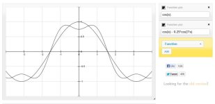
standard: y = A*cos(phi)
mov-midpoint: y = A*[ cos(phi) - 0.25*cos(3*phi) ]

Screenshot-16.jpg

you can see in the plot that even though A is the same for both, the moving midpoint has a lower amplitude and
can therefore put out a bit more signal (about 12% if I remember correctly).
When you look at the difference between two signals the 3rd order component (the 0.25*cos..) cancels out because
the 3rd order components are in phase as 0.25*cos(3*phi) - 0.25*cos(3*(phi+120)) = 0
 
Back
Top