Ebikes4Real
10 mW
- Joined
- Jun 26, 2016
- Messages
- 25
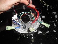
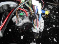
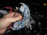
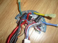
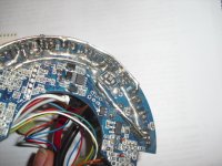
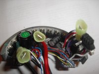
I've started to modify my BBSHD for more current. I've picked out the sealant, to get back to the PCB and I've found a few things:
1. The standard BBSHD controller is fitted with pretty low end mosfets from the factory (P75NF...). Not the same IRFB3077 as come fitted in the 750W BBS02. Hmmm, this might be easier than I expected :wink:
2. It comes standard with a pair of 5mohm shunts, so that means 2.5mohm equivalent resistance. Reducing the equivalent resistance by adding another 5mohm shunt, will mean an actual 45A limit (with 30A programmed), and you can of course, add more shunts, to further reduce the total shunt resistance (reducing the shunt value to 50% of standard, means the controller will deliver 2* the current, therefore double the programmed current limit). I think 45A is plenty, for plus 50% more power (3pcs of 5mohm shunt). All pretty straightforward so far.
I'll update with pictures soon.
Not suggesting this is something, that everyone should try. Definitely do not attempt it, unless you are reasonably skilled with a soldering iron, patient and go into it, knowing that there is a high probability you will wreck your controller. In fact, I suggest you enjoy the standard 30A instead. Pumping 50%, or more power, through this motor, is likely to break something, sooner or later (especially the gear train parts).
A few things to be aware of:
Firstly, it is easy to damage something when picking out the sealant. Secondly, it is rather tricky to remove the mosfets, without damaging the PCB (the way they are fitted from the factory makes it quite difficult to remove the original fets). Thirdly, the rest of the motor isn't going to stand up to a lot more power than the standard 30A (~1500W max), if it is used hard. 12pcs of IRFB3077 seem to be able to reliably provide around 40A max current, so a little more should be possible, but much more and you risk blowing a fet. I'm thinking a 45A limit will do nicely.
I do repeat, it is not a great idea to do this and it will void your warranty. If you are going to do the same, be nice and don't expect your supplier to fix it under warranty, when things start breaking