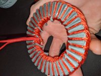
APL's DIY axial-flux motor

I made three identical blocks for the magnetic test,.. hope this is what we need.  The SMC and steel cores are identical,
and the Lam core is very close. I know we don't need the lam., but it might be interesting anyway, and it's already made.
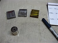
Test cores.jpg

First, I weighed them, and then I did a simple test of through-flux, using a big 1 inch neo that I have. The gauss meter 
probe is sensitive to where it's placed on the magnet, and will change dramatically in a small area, so I can only get
average numbers.
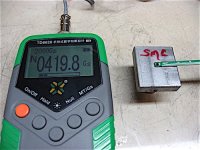
Magnetic tet 1.jpg

Weight; Steel- 105g SMC-88g Lam.-85g

Gauss through the top; 
SMC- 420
Steel-365
Lam-730

Length;
SMC-850
Steel-830
Lam-650

Width;
SMC- 850
Steel-850
Lam-1250

Interesting, but doesn't really tell us too much, except that they're all pretty close, and the lam's appear to be better
at transferring flux along their length, or thin side, but not through the stack. 

The coil test is what we really need, so I'll wind them up with some wire and go from there. Any ideas?  I don't have
much for power supply's, so I was thinking maybe car battery, heavy wire, and some big resistors. :?:
Start with a power up, and gauss test?
 
Can you do a pull test with your existing samples? Pull at about 1mm gap would tell us something. I think you did this already?
Another simple test is to place a couple of shims between the magnet and the iron that have a spacing big enough for your probe and measure the flux between the magnet and the iron. This will tell us about the same as the pull test but looks easier to do. The center of the magnet should be the highest flux spot.

A car battery and some big resistors will work but you would want to measure the current. Current and the number of turns are all that count. With a resistor, the current will tend to drift as it heats up. You don't need it to be on very long so hopefully nothing overheats. You probably want to shoot for some pretty high currents. If you have a lot of turns, you won't need as much current to reach saturation.
 
Yep, I'll do the pull test, I think it's the best way to see any difference between the samples. It will take a few days to
get it rigged up though, lot's of stuff to build and figure out. I don't have an ammeter, so I hope I can use the CA and an
extra shunt I have to run the power through.

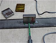
The static gap test with spacers was easy to do though, so I gave it a try with a 60mm bar magnet, let me know if this
isn't correct. The magnet and iron by itself was 2220 G, and all three samples tested the same at 4600 Gauss. (1mm gap)

Gap test..jpg

Measuring magnets isn't consistent, and none of these readings are any where near the 1.2T (12,000 gauss) that a Neo is
supposed to have,.. which is confusing. The K&J magnets website has an explanation for this, and some nice calculators
that clear things up a bit.

K&J website, 'measuring magnets'; https://www.kjmagnetics.com/blog.asp?p=measuring-magnets

The meter probe and hall sensor are to blame for some of it, and the magnets physical form and various flux areas do too.
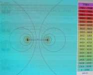
They have a magnet calculator that you can put in the dimensions of your magnet and get a FEMM reading, that matches
what I'm seeing. (2220G in the center)

K&J Magnet FEMM. 60x10x3mm.jpg

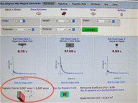
I see that they also have a magnetic gap calculator, but when I crunched the numbers it didn't quite match my readings.
Maybe their only measuring at that distance, and not against a gap with steel.

K&J Calculator - gap..jpg

So, I'll keep on keep'n on, but the good news so far is that the SMC doesn't suck yet, and is holding it's own with the other
samples.
 
That's encouraging. Your test setup looks correct. The reason you are only getting part of the maximum listed flux is your magnetic circuit is not closed. This is OK for this test, although it might be nice to measure what it takes to saturate the sample. If you put another bar magnet on top of the sample (attracting), it should increase the reading a bit.
 
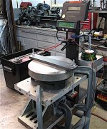
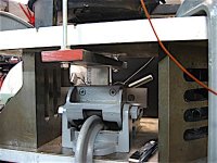
Heres the "apparatus",.. and why I always say, "you can never have to many C-clamps". :)

Pull test fixture..jpg

Core vise..jpg

Almost ready to go, I made a resister out of the old V1 coil wires and was able to get it up to 350 watts, but she heats up
pretty fast. I'll put a few more winds on the resistor, and a big push button switch, I'm not sure what were going to need..
but I can add or subtract winds, and this should give it a good starting point.

Just a few more tweaks, and I'll wind the cores with 10 or 20 turns and see what happens. Not sure if I can get it to
saturation with 12v, but I can use another 12v battery for 24v that should do it, if need be.

Fingers crossed, and fire extinguisher handy.. :confused:
 
Trouble, as usual. The 1mm gap snaps shut because the scale moves too much. I was hopping that wouldn't happen.
But it does,.. so I took the readings at 5mm for the first test. I'll try to narrow the gap, and get a better average.

Doesn't look like I can do a straight pull with this set up, it's looking like it will have to be relative numbers. I can do
the fulcrum bar thing, like I did before, but that's still not actual numbers. Probably need to get more scientific with
a stress sensor of some sort.

I can take some gauss tests and see if they match what the pull numbers are showing though. I did a quick reading on
the steel sample, in the center, and it read 2800 G, which is a more than a Neo magnet has, so it might be over 1T.
But I'm just guessing, and need to take all the readings yet.

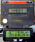
Anyway, for the first round.. with 23 turns at 5mm, Steel was 1499g pull, SMC was 1049g, and Lams were 999g.
All at a 230w and 10.7v, average.

Steel  1499g 10.7v 230w.jpg

Looks like steel pulls ahead, and the SMC and lams are tie. Hang in there SMC!
 
It seems like the SMC is at least in the ballpark.

It's going to be hard to prevent things from moving with that much force. A lever arm with one end on the scale will work and will reduce the travel by the ratio of the lever. Another approach is to let it stick with a 1mm non magnetic shim, then see how much force it takes to pull it apart. A peak reading scale would be real handy for this but I've done it just by watching closely at the numbers and repeating a few times to get an average.
 
Thats a good idea, I can try that,.. add shims and tighten the screws until it pulls away. I can take videos to record the
moments and take an average. Worth a try anyway, if I can do it fast enough before things heat up to much.

Yea, they are definitely strong little electro magnets! Hopefully I can still use this scale. The calculator says that a Neo
magnet with this face size, (40x10x3mm), has a pull of 6.6 lbs at 1mm, or 2993g. This scale has a 6000g range.
 
Yup, new avatar. Might as well get something out of V1,.. she was a beauty, if nothing else.
 
After messing around for days trying to measure this, I finally have some results. I had to switch over to a digital floor
scale that's good for 400 lbs. A little less sensitive, but it got the job done.

The thing would never stay in the same place twice so I wound up turning it on, using a 1mm shim, and adjusting the
gap each time. The break-away test didn't turn out to good because it was to hard to 'feel' the point that it breaks
away. The scale readings change wildly within just a few thousandth's, so the numbers are never going to be correct,
but at least, in the ball park.

At 23 turns, 11v, 240w and 1mm;

Steel - 23 lbs.
SMC - 13.8 lbs.
Lams- 15 lbs.

I also did a Gauss test on them and they all measured between 800 and 850 G. in the center.

So, without lab equipment it's very difficult to get consistent results, but from all the tests that I have done it's looking
like the SMC is still a viable contender.

It's looking more and more like the V2 motor is likely flawed with a restricted magnetic path through the slots in the stator
plate. The two biggest mistakes that I made on this motor were the slots, and trying to make the motor too light weight.

Well, I think we've seen enough to say that this motor needs to move on to the old motor grave yard, where all old motors
go to die,.. and it's time to put any more effort and money into the V3 in-runner.

The V3 motor uses even more SMC in the back iron, so it's imperative to figure out if the SMC is a go before committing to
that build, and so far I think it looks like it is.

To be fair, I'll need to do one more test on a factory made and processed lamination stack, since this sample was my own
creation from .012 lams, and unprocessed. Have to make sure of that, or the information can be read two different ways.

I need to take a small intermission here though, as far as motor building goes. This thread is always open of course, but
the actual new motor building will have to wait for a month or so, while I switch over to building the new cruiser frame.
Plenty of time to discuss the next motor, and try to nail some things down.

Spring is here and I'm getting a little bummed because the bike isn't built yet. V2 has completely absorbed another winter.
 
Can I just say first, that I have finally found my people. I still have some reading to do, but I'm getting there. Back in 2019 on this post there were talks about toroidal motors, and also a picture about a modeled stator core that I couldn't help but respond to.

I have been reading about axial flux motors for a while now (as you all have) and read many of the same articles that have been linked here. I am fascinated with Ben Katz's motor (coreless axial flux with the carbon fiber and halbach arrays). This inspired me to dabble in this witchcraft.

Here's a picture of a stator core I modeled and printed. It's super similar top the one posted by coleasterling in Oct 2019 ( but I promise I did it before I saw your post), just thought it was neat they are so similar. Ultimately I didn't use it and proceeded with the toroidal style.
PXL_20210410_031232796.jpg

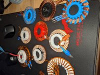
I went about it with 3d printing as was suggested, and have slowly iterating on a design of a toroidal stator, 3d printed at that. Yeah, like with plastic. I have made 4 working motors so far. one of which was actually pretty good. but eventually the epoxy I used to hold a magnet gave way to heat I think and started hitting the stator.

I am currently working on a larger version with a few more turns. But I included another picture of all my iterations on the toroidal style.
PXL_20210410_031148423.jpg

Here is my most recent stator, which I broke due to being to aggressive with a part that didn't fit. Oops!
PXL_20210410_033718006.jpg

This post has me inspired as well, and I'm thinking I'll make my own thread too. Thanks for your dedication in documenting the journey.

Here's my YouTube channel I recently started. I only have two videos, but you can see the last working motor spinning here:
[youtube]I91ciNn_HcY[/youtube]
 
Welcome! Nice looking stators. You have even more iterations than APL.

Now we need to figure out how to 3D print that SMC magnetic stuff.
 
Awesome HalbachHero! Sorry I've been AWOL for a while, I've been busy in the build section with another project.
This motor building can get on your nerves after a while,.. they have harts made of cold steel you know.. :lol:
I just need a few days off. :wink:

I'm glad you posted your Youtube channel, I wasn't sure which one it was,.. unfortunately your pictures won't load
on my PC, and I'd like to see them! I think you need to keep the kb down to around 150 kb. or so.

Welcome to the Sphere! This is definitely you place! And for sure,.. start a thread, we need more builds here! :thumb:
 
APL said:
This motor building can get on your nerves after a while,.. they have harts made of cold steel you know.. :lol:
Except for the heartless...I mean coreless ones. ;)
 
I like the idea of a 3d printed motor but what scares me is the tolerances.

I watched a video where a guy couldnt make a circle pull a vacuum due to the movement error of the printing machine nozzles circles circleness, i get the more profesional printers will have a tighter tolerance but surely they would still need to be spun and machined true for circles, i like what you have done becuase the axial motor the flat plain is the important one and for that 3d printing is good.

I was also watching laser abliteration balancing a rotor with software alone its enough to take a rotor spin it to high speed then remove any harmonic noise to the point its balanced so well its silent to the ear.

I bet the laser abliterator would do a good job of balancing the plastic print axial
 
Kinda out there, but I could see crushing up the SMC and blending it into some PLA pellets. Getting the ratio of SMC to PLA high enough would probably be troublesome.
 
Coleasterling,

I have used this on a test stator core
https://www.matterhackers.com/store/3d-printer-filament/proto-pasta-magnetic-iron-pla

It was not the best test, but it did show promising signs of of improving induction, but its only PLA, and I usually use PETG for these prints as its melting temp it higher, its doesn't go soft as quickly. and it has better layer adhesion which can prevent the rotors from exploding.

Also once you start talking about printing metal, the temps and abrasiveness becomes an issue for most out of the box printers. I use a Creality CR10 that I have improved overtime, but it still is limited to PETG. Nylon is a bit out of reach until I get an enclosure, and ABS is too toxic for me to touch if I don't have to since I'm not venting and sit next to my printer all day.

I can only hope that advancements in material science and the proliferation of 3D printing will lead to more widely available printable materials. Time will tell I guess. Until then air core all the way!
 
APL said:
It's been a while since I took a close look at the controller, I was surprised to see that it's not what I thought it was.
Since Crystalyte never did make it easy to tell them apart, I had to do a little research to figure it out. Looks like an
old 12 mosfet 40 amp, 36/48v model. I could have swore that it was the 72v 50A unit.

Well, I'll be buying a bigger controller for the new muscle cruiser project anyway. I bought this one used from HPC, so it
may be that the limit has been altered, otherwise I assume it would be 40A. I see that it has a USB input, but I'm not sure
if it's user, or factory access. Does it work off the USB voltage, or does it need to be powered up?

Dude, please.... This beautiful motor deserves much better than a crappy 50Amps controller!!!
At least throw in a 100Amps controller in there!

If you were in China I would happily give one to you, so you could test in proper conditions
 
Yea, I'm looking into it, but my battery supply is pretty meek at the moment. And looking through controller's, trying
to balance 'want', and 'need', is difficult. Most of my motors are sensorless, and most of the FOC controllers are hall.
It would be nice to have programable FOC for motor building, just makes it easier, and theres more control, plus, I
think the bike might be smoother with one, but I'm still going back and forth with the idea.

Then theres the price bite, and if I go for a cheaper one, did I just waste the money I could have used on a better one?
Mostly I just don't need a big controller yet, so it's still in limbo. The mid drive set up can do an awful lot with 50A.

Anyway, I'm going around and around with it,.. when I get the new bike built I'll have a lot more amps to fool with, and
I'll have to get more serious,.. but your right, it's going to come down to a 100A sooner or later, so I should plan on it.
Thanks for the offer! :) :thumb:
 
Cheap foc controllers are fine on a cheap build with cheap motor components etc to match.

What you need is a fine wine of a controller to tickle the motors phases and get it to sing from the bottom of its lungs.

Theres a heat managment and audio gain if nothing else from the more accurate phase control.

I guess its like listening to a tape then a flac file on a cheap set of headphones being a generic hub motor etc then comparing the same files on a theater system that would be the high end motor, the high end signals get the best gain from high end motors theater setups but the headphones benifit too.

Your builds are special i feel you need something decent to power them, i get cash is tight and 2021 is not going to be easy but if theres ones goal to set its that there will be a nice feeling of accomplishment at the end of this tunnel you keep at it.
 
Yea, cash is tight, with so many projects going on all the time,.. if I just stayed in bed I'd be rich! :wink:

I'll just sell something that I'm not using, when the time comes, and get something decent, like you say, "You get what
you pay for".

I'll get back into the ring soon enough, and double down on the next build. Hey, I found this machine that achieves exactly
the same results as motor building, but it's a lot easier to make! :lol:

kickingmyself.jpg
 
I totally disagree on the controller part. This motor should not be anything special in the ”difficult to control” department.

Get one of the bigger VESC if you want foc and programmability.

(And, if you want options.. If you can build a motor then you can also add halls. right?)

Trampa 75300 on a premium:
https://trampaboards.com/vesc-75v-300a--16s-c-1432.html

Flipsky 75200 on a budget: https://flipsky.net/products/flipsky-fsesc75200-75v-high-current-200a-esc-base-on-vesc-with-aluminum-heatsink-for-e-foil-fighting-robot-surfboard-agv-robot-arm

Don’t make it harder than it is :thumb:
 
Back
Top