You are using an out of date browser. It may not display this or other websites correctly.
You should upgrade or use an alternative browser.
You should upgrade or use an alternative browser.
DIY Toroidal Axial Flux PM
- Thread starter HalbachHero
- Start date
HalbachHero
100 W
- Joined
- Apr 5, 2021
- Messages
- 228
Thanks! its nice to see it running better, and without the bending. Feels like a real motor.stan.distortion said:Impressive! Congrats
Yes there is something quite satisfying about the waveform. I sometimes just hook it up and spin it just to watch it.mxlemming said:Fantastic. That sinusoid is sensational. Really nice and smooth.
That is the million dollar question. I have no idea what I want to do with it. The whole point of the tools I made along the way, was so that I could make more. So I intend to have do other projects with other versions of it, but I need to find a purpose for this one, and I'm not sure what that will be yet.mxlemming said:You're probably right... Balance it up, then find something to do with it. :lol:
I have considered:
- A generator, bike pedal powered, for fun, or a larger wind turbine. or a flywheel or combination of multiple of those.
- An e-bike
- A ridiculously overpowered RC car
- A large quad copter
Any other thoughts from the peanut gallery?
Another thing I would really like to do is find an elegant way of gearing this down. I really like the cycloidal gear idea, and I am considering pursuing that next. However, I also still think that concept would fit best on an in-runner style. So I have also considered trying that for factor out.
I was also able to put a smaller spacer on it. But I was not able to shrink it by 1.5mm like I thought. In fact it was only 0.5mm. Since the spacer has a 1mm overlap on top and bottom with the rotors, and the spacer being 10mm high. The air gap works out to about 0.75mm on each side. So the only reason I cannot get it closer is because the stator and the rotor are not perfectly parallel, and I'm not sure what the next step there is except having it machined.
Shrinking the air gap provided some nice improvements. I hooked it up to the scope and got the same reading as the photo before at a freq of ~31Hz. This calculates to just about 200Kv. that's ~10-20% improvement assuming some wiggle room from eyeballing the values. I also still have hope that there a better way to wind the stator so that the end turns do not end up as bunched up, and allow for fitting all of the strands that could possibly fit. I am convinced it's possible to get at least 6 turns, if not 7. I think that would lower the Kv to a pretty impressive point. I have also considered changing the number of strands to 15 or 10. There is also room for optimizing the iron backing. currently its still leaking a bit of flux out of the back.
I also played with shorting the phases and spinning it by hand. There is quite a bit more resistance than the previous motor.
A coreless motor is going to have the greatest advantage running at high RPM, which means you generally need a lot of reduction which tends to be lossy. Someplace I saw a cool magnetic epicyclic reducer. It used magnets on rings instead of gear teeth. There is an obvious limitation on torque, but you don't need any lube and there is essentially no loss in the "gears", just in the bearings.
Something like this might be combined with a more conventional secondary reduction to get the maximum torque up.
Your motor might be good for a large quadcopter. A wind generator application would probably want a lot more turns. If you wound one or two strands with as many laps as can fit, you should get quite a few turns.
It's really cool that you got it this far with printed parts. Great to see it actually running.
Vbruun
100 W
- Joined
- Sep 26, 2019
- Messages
- 294
Maybe you should consider the split ring compound planetary in stead of the cycloidal drive if you want to do an ebike.
I think it should be a bit simpler and no issues with vibrations.
As far as I can tell, the reduction can still be massive and the dilensions can be made so that IT can hold torque with 3D printed parts - I am a bit unsure whether it can be spun fast enough though.
I think it should be a bit simpler and no issues with vibrations.
As far as I can tell, the reduction can still be massive and the dilensions can be made so that IT can hold torque with 3D printed parts - I am a bit unsure whether it can be spun fast enough though.
mxlemming
100 kW
- Joined
- Jul 17, 2020
- Messages
- 1,120
Obviously i like ebike stuff, and i reckon you'd get away with a 2 stage belt reduction... Htd3m for the first stage and htd5m for the second given the plastic is likely to self destruct way before these belts.
Problem I've run into with printed gears in the past is that while they work initially, they melt once you start pushing them. With module 1.5, 30tooth and 60tooth reduction, 10mm wide, I found pla melts at the 100W 1500rpm range. You'll need much higher power rating (10x) than that for ebike even if your motor is only a few hundred.
If you go ebike, just bear in mind that you always need more power. No matter how much you have, you'll need more.
But a ridiculous RC car is a very good option too. And you could continue the 3d printing everything dream.
stan.distortion
1 kW
- Joined
- Jun 12, 2019
- Messages
- 377
Gearing losses are very high with printed gears too, a 3d printed hob to get them more accurate should be a doable and oil immersion would help with wear but it's a very long-winded approach. Cycloidal is an absolute no-go imo, you're basically running full sized high torque output gears at full speed low torque rpm's and will loose more than half your power, even with hobbed gears. Cycloidal isn't great even with precision ground gears, you may be able to do something with skate bearings as rollers (I think I have a drawing for that somewhere) but efficiency will still be far lower than a simple belt reduction. 3d printed epicyclic may be an option, without accurately finished gears it will still be more inefficient than belts imo but it will avoid side loads and that could be a deal breaker.
Can you do the spacers in multiple parts? If you can do them in multiple segments it should even out the non-parallel problem, not fix it but maybe good enough to live with. Failing that, hand finishing to correct seems like the only option :/ Shouldn't take too long, plastic and abrasives don't play well but a sheet of sandpaper on a sheet of glass should give reasonable results and re-printing the spacer with gaps/bridges between the bolt holes (so only the area around the bolts is making contact) could speed it up a lot.
Might be worth getting a clock gauge and making up something to mount it to the print head to get bed alignment set up accurately, ideally you'd design everything to just use the top face of a print so alignment is pretty much guaranteed but that's simply not possible in this case :/ Another thought, you could print the spacer in 2 halves (in width, height on the bed) and reverse them, match the front bed side face of one with the rear bed side face of the other, that should cancel out any non-parallelism.
HalbachHero
100 W
- Joined
- Apr 5, 2021
- Messages
- 228
fechter said:A coreless motor is going to have the greatest advantage running at high RPM, which means you generally need a lot of reduction which tends to be lossy. Someplace I saw a cool magnetic epicyclic reducer. It used magnets on rings instead of gear teeth. There is an obvious limitation on torque, but you don't need any lube and there is essentially no loss in the "gears", just in the bearings.
Something like this might be combined with a more conventional secondary reduction to get the maximum torque up.
Your motor might be good for a large quadcopter. A wind generator application would probably want a lot more turns. If you wound one or two strands with as many laps as can fit, you should get quite a few turns.
It's really cool that you got it this far with printed parts. Great to see it actually running.
High RPM would be ideal, but I dont have a lot of faith in this spinning much farther beyond 10k RPM, I worry about it blowing up. Perhaps with something with more metal, but inertia might be a concern.
I googled the magnetic bearing concept. I think I found something along the lines of what you were describing. I am curious about the idea, but it might be too exotic for this project.
I am definitely keeping a quadcopter on my short list. And thanks, the printer certainly makes it easy to rapidly prototype ideas. I wish I has a metal printer though
I think you are totally right on this. This seems like a simpler gear box to make that would be resilient enough. I think this is something that I could also prototype with a printer, but ultimately I would need something CNCd I may have a solution for that soon... Though I know very little about the specifics of gears, and I am not sure how I would go about engineering something that I could ensure would be solid, but thin and light weight, but trial an error has gotten me this far.Vbruun said:Maybe you should consider the split ring compound planetary in stead of the cycloidal drive if you want to do an ebike.
I think it should be a bit simpler and no issues with vibrations.
As far as I can tell, the reduction can still be massive and the dilensions can be made so that IT can hold torque with 3D printed parts - I am a bit unsure whether it can be spun fast enough though.
I would agree that a belt drive is the simplest thing to slap onto this to get it geared down. but it my never ending quest for micro optimization I want to strive for something more. This is already very thin, and If I can add a reduction and keep things thin, I would love to try. A hub motor on an e-bike would be a very nice win for me.mxlemming said:Obviously i like ebike stuff, and i reckon you'd get away with a 2 stage belt reduction... Htd3m for the first stage and htd5m for the second given the plastic is likely to self destruct way before these belts.
Problem I've run into with printed gears in the past is that while they work initially, they melt once you start pushing them. With module 1.5, 30tooth and 60tooth reduction, 10mm wide, I found pla melts at the 100W 1500rpm range. You'll need much higher power rating (10x) than that for ebike even if your motor is only a few hundred.
If you go ebike, just bear in mind that you always need more power. No matter how much you have, you'll need more.
But a ridiculous RC car is a very good option too. And you could continue the 3d printing everything dream.
If I assume that this thing can spin at 10k RPM. that's still to be determined, I have only gotten it up to 4k with the 16v. Then I could gear it down for a bike with an 20:1 reduction, would be about 40 MPH which I think is a nice top end. Though I haven't done all the math yet to understand if the motor could handle it, but I think that if it is capable of 10k RPM @ 240Kv would be 41V and if it survives running @ 32A then its possible that it could 1.3Kw, which I understand I will always want more, but if I could get that kind of power out of a homemade motor, I would be impressed.
In the process of trying to crunch some numbers, I came across this calculator, which given some losses and a 1% grade, 40mph would take something like 1.4Kw of power, which is a really fun coincidence. I just need to understand if it has the torque, which I dont quite know the Kt of this motor yet.
https://www.gribble.org/cycling/power_v_speed.html
Also in an effort to always improve. I thought of what might be a clever idea for making stators easier. I made what looks to be a torture device. I used a bunch of mini pins (23 gauge) and a 3D printed jig to make them go in straight-ish. Its not perfect. Also I coated the pins in some nail polish my wife never uses, to help prevent metal on metal contact. The idea is that I can wind the stator without needing to wrap around the stator toroidally. Cuz thats a hassle, and the hardest part of making these. And If I can wind it all, squish it flat and epoxy it, I can certainly get more turns for the same thickness. Rigidity is obviously a concern with this design, so we will see how it goes.
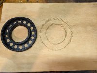
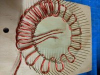

The litz wire machine ran out of wire again, time to respool it. its not hard but 20 spools @ 1000 turns each is a little too mind numbing for me, so it takes a while.
HalbachHero
100 W
- Joined
- Apr 5, 2021
- Messages
- 228
stan.distortion said:Gearing losses are very high with printed gears too, a 3d printed hob to get them more accurate should be a doable and oil immersion would help with wear but it's a very long-winded approach. Cycloidal is an absolute no-go imo, you're basically running full sized high torque output gears at full speed low torque rpm's and will loose more than half your power, even with hobbed gears. Cycloidal isn't great even with precision ground gears, you may be able to do something with skate bearings as rollers (I think I have a drawing for that somewhere) but efficiency will still be far lower than a simple belt reduction. 3d printed epicyclic may be an option, without accurately finished gears it will still be more inefficient than belts imo but it will avoid side loads and that could be a deal breaker.
Can you do the spacers in multiple parts? If you can do them in multiple segments it should even out the non-parallel problem, not fix it but maybe good enough to live with. Failing that, hand finishing to correct seems like the only option :/ Shouldn't take too long, plastic and abrasives don't play well but a sheet of sandpaper on a sheet of glass should give reasonable results and re-printing the spacer with gaps/bridges between the bolt holes (so only the area around the bolts is making contact) could speed it up a lot.
Might be worth getting a clock gauge and making up something to mount it to the print head to get bed alignment set up accurately, ideally you'd design everything to just use the top face of a print so alignment is pretty much guaranteed but that's simply not possible in this case :/ Another thought, you could print the spacer in 2 halves (in width, height on the bed) and reverse them, match the front bed side face of one with the rear bed side face of the other, that should cancel out any non-parallelism.
Missed a response. My bad!
Side loads are a concern, If I rotate it while its turning it starts to rub somewhere, so I know side loads will be a big problem. This is why the epicyclic gear sounds appealing. I think you all have talked me out of the cycloidal gear, though I will still probably print one to learn/play with.
I really like your idea on how to solve the printer issue. I will definitely see what I can do about getting things "perfectly" aligned. If I can solve this, I could certainly shave off more space even in its current form.
I am curious what you mean about the spacer. I originally had it going all the way around because the rotors bent a lot, but with the iron behind everything might keep it rigid enough that I could reduce the size of it to a bridge or make smaller separate objects. However I am curious why you think it will speed it up "a lot" I imagine it would reduce its inertia, but I don't think it would be by much. I think the entire spacer weighs about 10g.
Thanks for all the input!
stan.distortion
1 kW
- Joined
- Jun 12, 2019
- Messages
- 377
Sorry, I meant speed up hand-finishing the parts to get them parallel, not increase rpm. Any thoughts on balancing? Getting up to 4k rpm without balancing is impressive, it will be interesting to see how well it can hold together at higher revs. I've had a 100mm drum fan close to 10k rpm, over 100 hours running with no issues but it weighs practically nothing. Wouldn't be one bit surprised if it holds together just fine at those speeds though, 3d printing is a constant source of amazement 
mxlemming
100 kW
- Joined
- Jul 17, 2020
- Messages
- 1,120
HalbachHero said:Also in an effort to always improve. I thought of what might be a clever idea for making stators easier. I made what looks to be a torture device. I used a bunch of mini pins (23 gauge) and a 3D printed jig to make them go in straight-ish. Its not perfect. Also I coated the pins in some nail polish my wife never uses, to help prevent metal on metal contact. The idea is that I can wind the stator without needing to wrap around the stator toroidally. Cuz thats a hassle, and the hardest part of making these. And If I can wind it all, squish it flat and epoxy it, I can certainly get more turns for the same thickness. Rigidity is obviously a concern with this design, so we will see how it goes.
resized-image-Promo (77).jpeg
resized-image-Promo (78).jpeg
resized-image-Promo (79).jpeg
The litz wire machine ran out of wire again, time to respool it. its not hard but 20 spools @ 1000 turns each is a little too mind numbing for me, so it takes a while.
This is pretty interesting. You'll get really good copper density and I'll bet it's far stiffer with solid epoxy and copper, no pla and air. Higher temp operation too.
If you put a load of polypropylene sheet above the wood and 3d printed some super thin walls you might be able to mould in situ.
You do know the Kt by the way... Just convert Kv to SI units and invert. See the link i sent a while back.
I built a3d printed turbine blade a while back btw. 80mm diameter and it easily spun up to 16krpm without self destructing. I might put it in a plastic bowl and see how fast it'll go before exploding.
APL
100 kW
- Joined
- Aug 6, 2018
- Messages
- 1,113
Just wanted to say congratulations for your well earned success! :thumb: The motor is working awesome, and 4K rpm is
crazy for an unbalanced 3D printed motor! I also love your new idea for a stator & hope that works better for you.
Things are looking up, and now you need to start thinking about what to do with these things, he, he,.. well we should
be able to help with that! :lol:
The high rpm of your motor reminded me of the model airplane 'jet' motors that produce lots of thrust, and can use even
more rpm! (Maybe not for bikes per say,.. but might be a posible direction to go.)
I still like Thecoco's tire-drive idea, maybe a dual motor center drive,(no need for gearing), for a simple approach anyway.
Anyway, don't listen to me,.. just keep up the awesome work!
Electric Jet; https://www.youtube.com/watch?v=nu9Kst9tPgw
mxlemming
100 kW
- Joined
- Jul 17, 2020
- Messages
- 1,120
I just did an experiment with a 120mm 3D printed rotor (turbine design for an air pump) spinning it up as fast as I could.
It hit 1250eHz = 75000erpm = 10700mech rpm. Since it was pumping air, it didn't want to spin any faster without tripping my 250WPSU.
I guess you are pretty good to go then with your 4k rpms.
[youtube]5kMioSEDfGE[/youtube]
It hit 1250eHz = 75000erpm = 10700mech rpm. Since it was pumping air, it didn't want to spin any faster without tripping my 250WPSU.
I guess you are pretty good to go then with your 4k rpms.
[youtube]5kMioSEDfGE[/youtube]
Thecoco974
10 W
- Joined
- Dec 7, 2016
- Messages
- 94
Good work on the carrierless stator ! It's probably the best way to get good copper density with proper compression tooling and vacuum infusion of high temp epoxy 
APL it's funny you mentionned the symetrical coreless outrunner friction drive since it was my first design who was'nt build last year due to Covid.
It may still be tested if my school machine shop find some time to give it a go.
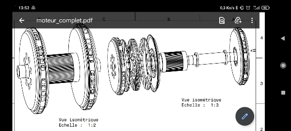
About your 3D printer Turbine it looks pretty well balance ! My concern with the 3D printed stator is the centrigugal force the magnets apply to the plastic at high speed, even when balanced I think it may still limit the max RPM.
Envoyé de mon Redmi Note 9S en utilisant Tapatalk
APL it's funny you mentionned the symetrical coreless outrunner friction drive since it was my first design who was'nt build last year due to Covid.
It may still be tested if my school machine shop find some time to give it a go.

About your 3D printer Turbine it looks pretty well balance ! My concern with the 3D printed stator is the centrigugal force the magnets apply to the plastic at high speed, even when balanced I think it may still limit the max RPM.
Envoyé de mon Redmi Note 9S en utilisant Tapatalk
HalbachHero
100 W
- Joined
- Apr 5, 2021
- Messages
- 228
Back from vacation. while I haven't been making actual progress lately I have been thinking a lot about things, and keeping up to date with everyone's posts.
so 0.75v @ 180RPM
if 180RPM = 18.849 rad/sec
then Kv = 0.75V / 18.849 rad/sec = 0.03978 V/(rad/sec)
and if Kt = Kv
then Kt = 0.03978 (N*m)/A
and if I know max current is ~32A that also means that max torque would be something like 1.273Nm.
cool!
And I agree, the forces that the magnets apply to the outer diameter of the rotors will be intense at high RPM, but I think that them being magnetized and epoxied to the washer give it quite a bit of strength, and although its plastic, its almost all walls, making hopefully as tough as it can be. I'm more worried about the plastic holding the hub in place failing first, but we will see!
I am hoping to be able to double the number of turns with the plastic entirely out of the equation, but I think that there will be some issues with the organization of the legs, the wire naturally takes a different path around a corner. As the leg makes the end turn, depending on if it is going toward the inner or outer diameter, it will round it differently. This seems to make some legs seem closer than others. I wonder if it will affect performance, or if this is something that was always present. The main difference I can tell is that I cannot pull the wire as tightly in this new style than I could around the plastic core.
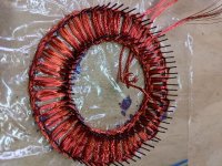
I was able to re-spool the litz wire machine again and spooled 3 of the smaller spools full of 20 strand untwisted litz. I then added more of the nail polish to the pins to ensure they were fully covered, in a test wrap, they seemed to still have metal on wire contact. Then I placed a half of a plastic bag down and pushed it over the pins. In hindsight I should have put that down first and put the pins over it, but you live and you learn. I am sure that will affect how it ultimately comes off in the end, but we will see.
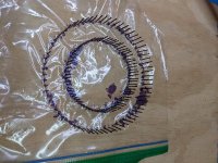
I was able to get two laps done tonight with each phase. I will see how far I can get tomorrow.
I see what you are saying now. That makes a lot of sense. I can certainly try that method, it is probably easier.stan.distortion said:Sorry, I meant speed up hand-finishing the parts to get them parallel, not increase rpm.
Yes you're right. I went back and re-read thatmxlemming said:You do know the Kt by the way... Just convert Kv to SI units and invert. See the link i sent a while back.
I built a3d printed turbine blade a while back btw. 80mm diameter and it easily spun up to 16krpm without self destructing. I might put it in a plastic bowl and see how fast it'll go before exploding.
so 0.75v @ 180RPM
if 180RPM = 18.849 rad/sec
then Kv = 0.75V / 18.849 rad/sec = 0.03978 V/(rad/sec)
and if Kt = Kv
then Kt = 0.03978 (N*m)/A
and if I know max current is ~32A that also means that max torque would be something like 1.273Nm.
cool!
That's good news. Obviously there is a bit more force at the the same RPM on the motor given the magnets, but I think that them being epoxied to the steel washers helps hold it all together. I may be using the incorrect term, but it wobbles on its axis, maybe that is not balance, but I believe stan.distortion is right, using standoffs instead might be an easy way to fine tune that. And for the same reason, the washer might give it enough stability that I don't have to worry about bending. If it works, it would provide more airflow as well.mxlemming said:I just did an experiment with a 120mm 3D printed rotor (turbine design for an air pump) spinning it up as fast as I could.
It hit 1250eHz = 75000erpm = 10700mech rpm. Since it was pumping air, it didn't want to spin any faster without tripping my 250WPSU.
I guess you are pretty good to go then with your 4k rpms.
Thanks, but I know it can be improved on yet, but yes very happy to see another one working. It still fascinates me every time.APL said:Just wanted to say congratulations for your well earned success! :thumb: The motor is working awesome, and 4K rpm is
crazy for an unbalanced 3D printed motor! I also love your new idea for a stator & hope that works better for you.
Thanks! We will see how it turns out. Could you elaborate on what you mean by vacuum infusion? I am not sure how I intend to get epoxy fully integrated with in the wires, but I was hoping I could just encase everything in epoxy. I saw in your post, that you used the 3D printer bed to cure it. I wonder if I could do something like that while its clamped down too....Thecoco974 said:Good work on the carrierless stator ! It's probably the best way to get good copper density with proper compression tooling and vacuum infusion of high temp epoxy
About your 3D printer Turbine it looks pretty well balance ! My concern with the 3D printed stator is the centrigugal force the magnets apply to the plastic at high speed, even when balanced I think it may still limit the max RPM.
And I agree, the forces that the magnets apply to the outer diameter of the rotors will be intense at high RPM, but I think that them being magnetized and epoxied to the washer give it quite a bit of strength, and although its plastic, its almost all walls, making hopefully as tough as it can be. I'm more worried about the plastic holding the hub in place failing first, but we will see!
I am hoping to be able to double the number of turns with the plastic entirely out of the equation, but I think that there will be some issues with the organization of the legs, the wire naturally takes a different path around a corner. As the leg makes the end turn, depending on if it is going toward the inner or outer diameter, it will round it differently. This seems to make some legs seem closer than others. I wonder if it will affect performance, or if this is something that was always present. The main difference I can tell is that I cannot pull the wire as tightly in this new style than I could around the plastic core.
I was able to re-spool the litz wire machine again and spooled 3 of the smaller spools full of 20 strand untwisted litz. I then added more of the nail polish to the pins to ensure they were fully covered, in a test wrap, they seemed to still have metal on wire contact. Then I placed a half of a plastic bag down and pushed it over the pins. In hindsight I should have put that down first and put the pins over it, but you live and you learn. I am sure that will affect how it ultimately comes off in the end, but we will see.

I was able to get two laps done tonight with each phase. I will see how far I can get tomorrow.

HalbachHero
100 W
- Joined
- Apr 5, 2021
- Messages
- 228
Oaky, well I was able to make a bit of progress, and learned a few things. I managed to get 5 laps around the pins with the three phases, I could have done more but decided not to overdo it. I will certainly make another stator. With 5 laps it started to become somewhat difficult to keep the wirer down while I wound thing around, and over time pulling things tight was pulling the pins inward. Obviously I need this to keep its shape, so I pushed the pins out. This helped keep the wire down and keep the shape of the stator.
After a while I realized that I did not need all the pins that I had and was able to remove half of them. I removed them after I was done winding it, but I imagine this would make it easier to work around. Also, easier to set up in the future given that I have to hammer in half as many nails (72 less to be exact)
I also found that due to the pattern of where the wire crossed over, the diameter of the pin dictated the gap between two of the wires. I decided on the next set up I will use the larger diameter pins I bought for the outer diameter of the jig. The inner diameter benefits from keeping things tight, so I will use the smaller ones still. I am hoping that I can use the larger pins to pull things straight too, without bending them.
Once I wound things up used a jig I tried to used to help make the rotors that I had laying around, and it fit nicely to push down the middle of the stator between the pins. I clamped this down as hard as I could and folded the pins down pushing the end turns down a bit more too. Then I un clamped it and mixed up the entire contents of a high heat epoxy that I purchased. I was not ready for this, but after mixing things up for about 30 seconds, about 1 minute passed and it got really hot and started steaming in the plastic cup I had it in. the epoxy seemed to have immediately cured in some sort of thermal runaway event. I brought the cup outdoors and turned on a fan and left for a bit.
I came back a bit later and added a bit more epoxy (not the high heat stuff, since I ran out). This filled all the gaps and I used the Jig again to press everything down. I let that cure for about 2-3 hours. When I went back I tried to carefully remove the excess epoxy and pull out the clips. The clips were in there pretty good, but I was able to lever them out without damaging the stator. Unfortunately however, there was damage from clamping things down with the pins still in I think. I have seen at least 2 strands that have been severed at some point.
Currently it weighs 70g, which means there is no weight savings, obviously the epoxy fills the voids and adds quite a bit of weight. But the really neat thing is that the whole thing is about 6.5mm, which was the target thickness. The inner part however is ~2mm thinner with the same amount of turns.
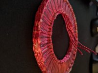
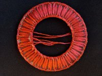
Obviously this means I need to make another one with more turns. but it also means I need to find something to do with those end turns to flatten things out, or I will need to somehow make more room to accommodate the stator being thicker on the inner and outer diameters. I think I can only get away with that on the inner diameter. The outer is where I need some integrity.
I have started designing a new jig to make set the pins at an angle, and using the larger pins on the outer diameter. Also there will be a raised part in the center diameter where it will allow for the end turns to overhang on the bottom as well as the top to even things out a bit more. I can print another one after to clamp it together.
After a while I realized that I did not need all the pins that I had and was able to remove half of them. I removed them after I was done winding it, but I imagine this would make it easier to work around. Also, easier to set up in the future given that I have to hammer in half as many nails (72 less to be exact)
I also found that due to the pattern of where the wire crossed over, the diameter of the pin dictated the gap between two of the wires. I decided on the next set up I will use the larger diameter pins I bought for the outer diameter of the jig. The inner diameter benefits from keeping things tight, so I will use the smaller ones still. I am hoping that I can use the larger pins to pull things straight too, without bending them.
Once I wound things up used a jig I tried to used to help make the rotors that I had laying around, and it fit nicely to push down the middle of the stator between the pins. I clamped this down as hard as I could and folded the pins down pushing the end turns down a bit more too. Then I un clamped it and mixed up the entire contents of a high heat epoxy that I purchased. I was not ready for this, but after mixing things up for about 30 seconds, about 1 minute passed and it got really hot and started steaming in the plastic cup I had it in. the epoxy seemed to have immediately cured in some sort of thermal runaway event. I brought the cup outdoors and turned on a fan and left for a bit.
I came back a bit later and added a bit more epoxy (not the high heat stuff, since I ran out). This filled all the gaps and I used the Jig again to press everything down. I let that cure for about 2-3 hours. When I went back I tried to carefully remove the excess epoxy and pull out the clips. The clips were in there pretty good, but I was able to lever them out without damaging the stator. Unfortunately however, there was damage from clamping things down with the pins still in I think. I have seen at least 2 strands that have been severed at some point.
Currently it weighs 70g, which means there is no weight savings, obviously the epoxy fills the voids and adds quite a bit of weight. But the really neat thing is that the whole thing is about 6.5mm, which was the target thickness. The inner part however is ~2mm thinner with the same amount of turns.


Obviously this means I need to make another one with more turns. but it also means I need to find something to do with those end turns to flatten things out, or I will need to somehow make more room to accommodate the stator being thicker on the inner and outer diameters. I think I can only get away with that on the inner diameter. The outer is where I need some integrity.
I have started designing a new jig to make set the pins at an angle, and using the larger pins on the outer diameter. Also there will be a raised part in the center diameter where it will allow for the end turns to overhang on the bottom as well as the top to even things out a bit more. I can print another one after to clamp it together.
mxlemming
100 kW
- Joined
- Jul 17, 2020
- Messages
- 1,120
This looks like you could get quite a lot of power out of it if all goes well. Reducing the thickness is going to gain a lot of magnetic strength and the extra copper fill you could get... This is actually getting into the realm of high density of copper and magnets.
Consider printing a jig and using 1.5 or 2mm taper dowels pushed in from the underside to make the pattern. Bit of silicone oil on the surfaces of the print and dowels and you can probably reuse the mould.
Also, while retracting my idea of the PCB as a coil former since this clearly ends up with higher density, how about in-moulding a milled PCB around the edge/in the center to mount it with fibreglass?
Bonus points for getting some hall sensors on it...
HalbachHero
100 W
- Joined
- Apr 5, 2021
- Messages
- 228
mxlemming said:This looks like you could get quite a lot of power out of it if all goes well. Reducing the thickness is going to gain a lot of magnetic strength and the extra copper fill you could get... This is actually getting into the realm of high density of copper and magnets.
Consider printing a jig and using 1.5 or 2mm taper dowels pushed in from the underside to make the pattern. Bit of silicone oil on the surfaces of the print and dowels and you can probably reuse the mould.
Also, while retracting my idea of the PCB as a coil former since this clearly ends up with higher density, how about in-moulding a milled PCB around the edge/in the center to mount it with fibreglass?
Bonus points for getting some hall sensors on it...
Thanks, I'm hoping so too. I think I came up with a clever way of mitigating the end turns in the stator so that I can flatten the whole thing out more.
The dowels idea is great. I will likely do something like that. the pins bend real easy so its a pain to get them all in nicely.
I like the PCB/fiberglass option for mounting, I may do that as well.
I am having some issues with my printer lately since I switched to a hardened steel nozzle. I am not quite sure what the issue is yet, but ill figure it out soon hopefully and be back at it.
HalbachHero
100 W
- Joined
- Apr 5, 2021
- Messages
- 228
I like your idea a lot. The only "issue" is that they will be stuck in the stator afterwards. it may be negligible weight. The other thought is that it will get under the plastic so both the pins and the plastic would have to be removed before curing the epoxy. But its easy to trash the plastic and reuse the pins.APL said:Just a thought, but maybe you can use some small heat shrink tubing on the pins, (without shrinking), or small plastic
straws, (coffee swillers?), to insulate the pins and make removal easy?
Stator is really looking great!
Currently I am 3d printing a jig that will hold the pins. I am sure that it will get resin on it after the next stator, but I plan to experiment with different materials and epoxy to find an easy non-stick solution.
I have another question for the community too. If I have an iron back on my rotor, if it had a smaller diameter on the inner diameter than the magnets or vice versa on the outer. I guess an overhang. Would that have a negative effect on things?
HalbachHero said:I have another question for the community too. If I have an iron back on my rotor, if it had a smaller diameter on the inner diameter than the magnets or vice versa on the outer. I guess an overhang. Would that have a negative effect on things?
Other than a tiny bit of extra weight, I don't think it would have any adverse effect. There won't be much magnetic flux in the overhanging part.
HalbachHero
100 W
- Joined
- Apr 5, 2021
- Messages
- 228
fechter said:Other than a tiny bit of extra weight, I don't think it would have any adverse effect. There won't be much magnetic flux in the overhanging part.
Cool, I'm thinking of ways to change the back iron and use it as a structural piece more than it is currently.
I don't have a ton of progress lately. but I made a jig for the pins and got the first lap of each phase done. It took a while, like 30 minutes to wind one lap of all three phases. This jig has two pins for each point I had before, this makes it so I can turn each following phase in a slightly different point, which allows the wire to flatten out before passing over the other phase. The pins are offset by 3mm on bot the inner and outer diameter and by +/-1 degree from their original position as well. Also I have put the pins in at an angle and hammered them in (they are a fairly tight fit). This is nice, but it makes it difficult to really push the wire down tightly. Also the angle, and the proximity makes it tough to wind quickly because one of the 20 wires will often get snagged on an adjacent pin. I also put a spot in the jig that holds the beginning of each phase, this is working well. There is also a ring on the inner and outer diameter where I can add an insert that will create a wall to keep epoxy in when I am at that phase. For now I have stapled a square of plastic bag I cut out.
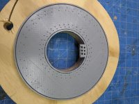
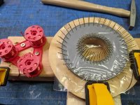
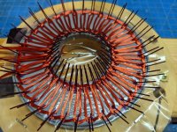
I think I will make some modifications to the jig to hold the pins at different levels and an easier system for holding thee starting wires. I found that the soldered wires were difficult to fit through the thing I designed. I also think I will find a way to coat the pins before adding them to the jig, as painting them with nail polish is a pain in the butt. It takes about 1.5-2 hours just to make a jig, and I think its only partially resuable. The pins and the painting are the time consuming part, and I don't believe those will be reusable. At least they are cheap.
I looked into getting ceramic pins. tapered dowels that small also seem difficult to come by at a reasonable price. I will probably want ~300. It will take 144 at least to do a single jig, but I think that's the solution to the reusability.
I will spend some more time soon working on the stator. but I think I only have enough wire on the spools to get about 5 laps again out of it. But if this one works out well with my fix for the end turns, and doesn't break too many strands, I will likely try to fix it to a hub and see how it performs. Then I think ill make the changes to the jig and respool things for a 8-10 turn stator. (hoping for about 6.5-8mm at that count)
HalbachHero
100 W
- Joined
- Apr 5, 2021
- Messages
- 228
Another update, but not huge progress.
I was correct in my suspicion I was only able to get 5 laps out of the wire left on the spools. I finished up winding the stator, but I still do not have more epoxy yet. Ill pick that up tomorrow. But so far this is looking really good. for the same number of turns as the Mk5, it is going to be quite a bit thinner.
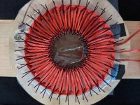
My fusion 360 trial expired, and I really dont want to buy it.... but I might.
I was correct in my suspicion I was only able to get 5 laps out of the wire left on the spools. I finished up winding the stator, but I still do not have more epoxy yet. Ill pick that up tomorrow. But so far this is looking really good. for the same number of turns as the Mk5, it is going to be quite a bit thinner.

My fusion 360 trial expired, and I really dont want to buy it.... but I might.
HalbachHero
100 W
- Joined
- Apr 5, 2021
- Messages
- 228
Vbruun said:As far as I can tell, you can just renew it
https://www.autodesk.com/products/fusion-360/personal
Wow thank you. I am not sure why It kept saying I needed to purchase it, or how I didnt find that page. I wonder if I started the trial with the wrong type of account or maybe they recently started offering the free version. Either way, thank you. That was super easy, and I'm back up and running.
Similar threads
- Replies
- 6
- Views
- 261
- Replies
- 129
- Views
- 4,163

