TorontoBuilder
100 W
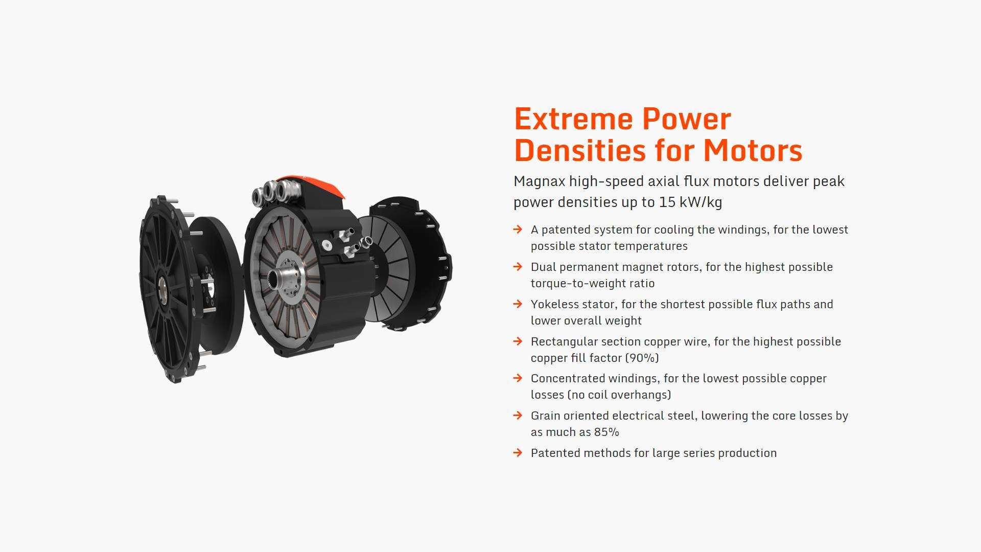
Ianhill said:magnax.png
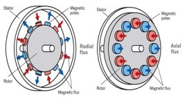
See how theres a jagged edge down the face without rounded edges, on traditional motors that would be hot spots on the steel.
Im aware the segments are built from laminations but they stack in a different oreantion theres a flat face of stator facing the magnets rather than edges face on.
These edges face the opposing coil im not expert but its 1 or a mixture of these 3 things help efficency, loeer high speed losses or smoother motor reduce torque ripple by sharing losses mutually coil to coil.
I see the jagged stepped stator lamination edges in the image you posted. No disagreement there, because I have a larger version of that artist's rendering that illustrates the stepped edge quite clearly.
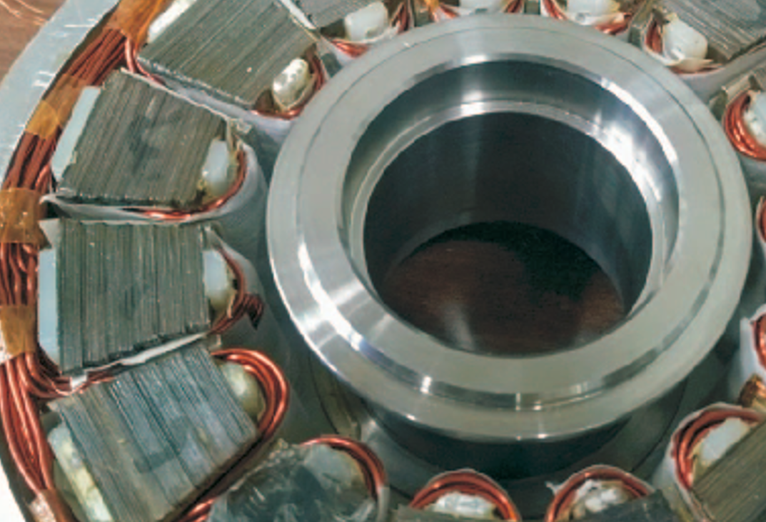
I'm fairly sure that does not represents the current 'as built" motors, because I have the following photos of actual built stators that do not show any jaggedness to the stator edge.
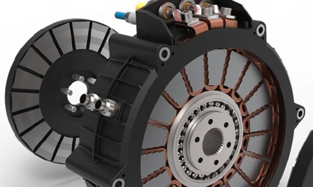
another construction info pic
I'm fairly certain that the artists rendering is from a very early magnax prototype, photos of which I posted earlier in this thread. Here is a closer view showing the crude 6 step stators held between plastic end pieces.
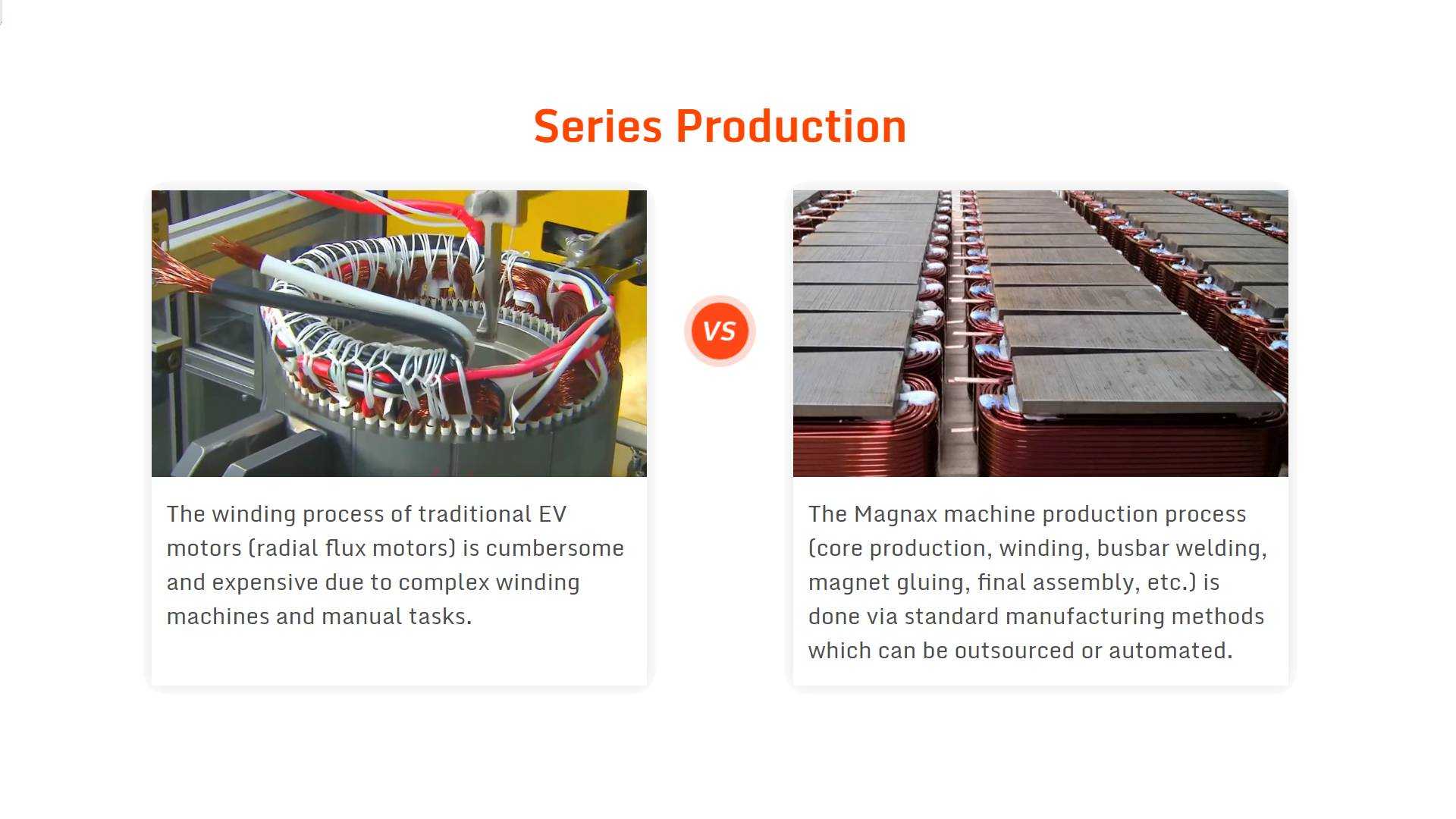
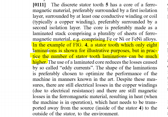
While other images with stepped sided stators were posted from the one patent document, they are merely an artist's rendering and not how the stator is actually built. This is clearly stated within the long form text description in the patent filings, which I have excerpted here:
and let's end this post with a gratuitous animated gif...
")