fredo gauvino said:
At first everything was perfect,
What, specifically and exactly, was changed between the time it was "perfect" and the time the problem started?
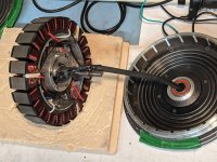
but just before relacing the motor, while measuring max engine rpm, I noticed that sometimes the motor would "vibrate" at certain positions. You could hear a loud thump, suggesting me that something was wrong. :?
What exactly do you mean by "loud" and what exactly by "thump"? To me, that phrase would be something like a book being dropped from a height and landing flat on the ground, or a fist on big wooden table, or a small explosion, or someone hitting my ribcage, etc.
If I heard a sound I could describe as a "loud thump" from a hubmotor, I would expect to see pieces of it strewn about.
")
I"m asking because if the sound is related to the problem, or causing a problem with operation, then knowing exactly what that sound is may be very important.
I myself wouldn't call it a "thump" but I have heard a sound from a motor with poor timing control of the phases by the controller, that would cause the controller to actually try to reverse direction instantaneously just for one cycle, and that can be rather loud. Some have had this and called it a bang, which may also be called a thump if it was a bit less loud.
This kind of timing problem is often caused by a problem with hall sensor positions, vs what the controller expects, but it isnt' likely to be the problem you describe further down with orientation; rather it is where the sensors are placed vs which phases and magnets interact for each cycle. Sometimes it is an offset, and sometimes it is directional (works fine with one rotation direction, problematic in the other).
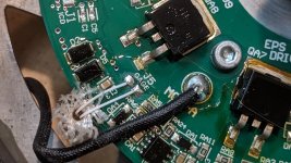
After ruling out the controller by testing with another one, I put some LEDs + 5k resistors on 3 phases signal and +5V, and I saw some glitches on the Hall Sensor signals while turning the motor by hand near the position where the thump was heard.

In order to test the halls, you would have to put the LEDs and resistors on the hall wires, not the phases. THe phases will only give much of a signal if you spin the motor relatively quickly, while the hall signals can be read this way with only single-magnet-position movements.
[youtube]https://youtu.be/hRlc6hcNoiQ[/youtube]
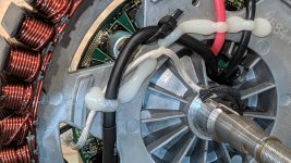
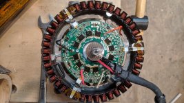
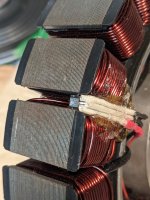
I don't hear any thumps in the video. I can hear what might be scraping of wires or windings on the covers. Is there abrasion of any kind on any of the wires, windings, or covers, inside the motor?
I couldn't tell what the hall signals were because the camera kept moving around, and the LEDs are dim, and I can't see the motor and the halls at the same time to see the relative changes vs the motor speed/rotation.
What is the specific "glitch" that you see? Is it a change in the pattern? If so, what pattern do you see, vs what you expect to see?
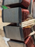
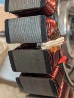
don't know , but could it be related to the hall orientation, as the hall sensors were loose and I had to epoxy them down.
One of the hall sensor is not 100% perpendicular to surface, could it be the problem ? Is the orientation important ?
It is unlikely to be that; there is significant variation in orientation in cheap hubmotors and they generally work ok. If it was very far off, it would probably not get a signal at all, or would have the wrong timing/etc. vs the other ones, all the time not just at one specific sound point.
You'd have to move the sensor to match the others to verify this though. (I would save that as a last step though).
https://photos.app.goo.gl/EPtug8nhKdHsCa627
I can't access the image. If you attach it to your post, anyone that can see the post can see the image.