Hi there,
New to the forum. Tried searching for a topic around my question but not luck.
Is there a way to tell if my throttles use HALL effect or if they are POTs? (Hopefully I'm asking this correctly)
I've converted a boat to be full electric using an out-of-the-box plug and play solution.
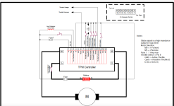
Each side (prop) is using an LMC D-127 electric motor. The motor controller I have software to is TPM400. (the starboard side has a sigma drive - long story)
The throttles are custom made in Denmark from a company that no longer exists.
I'm increasing the voltage of the boat to 72V using Kelly-KPM 4Q controllers,
The retailers of this kit concealed most of the throttle wiring with some rubber goop so I can't trace the wires. (another long story)
Anyway, I looked at the software set up for the TPM and I believe these are POTs but unsure.
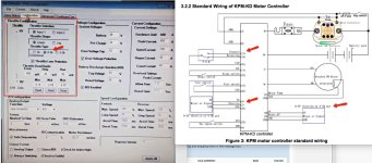
I've attached the TPM set up that shows 0-5k is selected (which seems odd because the throttles have forward and reverse- I would have thought Bi would have been the selection)
Also in the attachment is the kellycontroller wiring diagram that has a label for 0-5k POT.
Are the selected 0-5k and Linear options on the TPM software an indicator these are standard POTs?
Thanks in advance. Apologies if this question is mottled. I'm by no means and electronics engineer..


