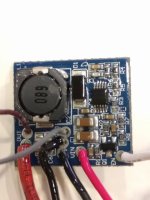
Hello all,
I can't find this information answered on the forum but there may be knowledge out there...
I have two questions regarding a controller model KT24/36SVPR-HRD01:
- Is there a microcontroller pin on the controller that switches state when the LCD backlight comes on and off? I'd like to use this to control bike lights.
- What is the difference between the 6 amp and 7 amp version?
To expand:
The PCB has what could be a part number 'KTE-6S3-D3c' with what looks like a possible date of 170521. This makes me suspect the board is a possible slightly revised version of the board described here: https://opensourceebikefirmware.bitbucket.io/development/Motor_controllers--BMSBattery_S_series.html
I'd like to add an external light output to this. My question looks to be similar to this one: https://www.pedelecforum.de/forum/index.php?threads/lichtausgang-am-s06s-controller.26833/ - and it looks as though I would need to construct something like the light control PCB described here: https://opensourceebikefirmware.bitbucket.io/development/Motor_controllers--Other_controllers--BMSBattery_S06P--various_info--02.html
Much as in the pedelecforum.de post, I can't seem to find an obvious PCB pin which changes when the light is switched on or off. I'm posting here in case anyone knows if there is a microcontroller pin that has this output and could be wired to? I didn't really have a probe small enough to probe individual pins.
I can't see a light pin listed on the schematic at https://opensourceebikefirmware.bitbucket.io/development/EmbeddedFiles/32-BMSBattery_S06S-Kuteng_EBike_motor_controller_schematic.pdf - but this might just not have been reverse engineered.
Related to hardware differences of lamp output vs no lamp output: I have two controllers - both with the same part number. However one has rated current of 6A and max current of 12A. The other has rated current of 7A and max current of 15A. They both use the same FETs (110N7F6) and same heatsink so I don't understand how the max current differs. Do the boards have a different shunt value, or do they have a different software version to limit current, or are they in fact the same? I'm just curious.
Thanks for help!


