Attempting to upgrade to 72V motor controllers but using my current throttles from a 48V system.
From what I understand the throttles are fine with a 72V system.
The throttles are/were custom from a company no longer available hence no wiring diagram.
These do not appear as normal pots as they have a circuit board in the housing rather than a wiper.
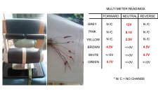
I took voltage measurements w/multimeter while they were hooked up to the 48v system in an attempt to reverse engineer.
Looks like I have a signal/F/R but not sure about the other wires reading 12, 9 and 2.5V
I spoke to Kelly Controls regarding a bi-directional setting called "joystick" and they have been pretty helpful until I got this answer which I have no idea what she means regarding the throttle starting at 2.5V?
"if you use joystick setting,you must set the throttle signal at 2.5V before power is on.
Otherwise it will report 2-4 code.Did you start the throttle from 2.5V position when you use joystick?"
I'm a hobbyist and not an electronic engineer so any help would be appreciated in helping me understand what I am looking at.
I've attached an image with my findings for one of the throttle controls.
Thank you!
From what I understand the throttles are fine with a 72V system.
The throttles are/were custom from a company no longer available hence no wiring diagram.
These do not appear as normal pots as they have a circuit board in the housing rather than a wiper.
I took voltage measurements w/multimeter while they were hooked up to the 48v system in an attempt to reverse engineer.
Looks like I have a signal/F/R but not sure about the other wires reading 12, 9 and 2.5V
I spoke to Kelly Controls regarding a bi-directional setting called "joystick" and they have been pretty helpful until I got this answer which I have no idea what she means regarding the throttle starting at 2.5V?
"if you use joystick setting,you must set the throttle signal at 2.5V before power is on.
Otherwise it will report 2-4 code.Did you start the throttle from 2.5V position when you use joystick?"
I'm a hobbyist and not an electronic engineer so any help would be appreciated in helping me understand what I am looking at.
I've attached an image with my findings for one of the throttle controls.
Thank you!