Hummina Shadeeba
1 MW
http://www.bavaria-direct.co.za/scheme/calculator/
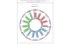
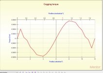
will more cogging steps per turn equal less cogging torque the motor will have?
will more cogging steps per turn equal less cogging torque the motor will have?

larsb said:Yes, it will

it looks hella risky with the teeth connected after winding and surely had taken development and not a nice out of the box option. ideal in ways for sure but the one person who i read from who had made a stator like that,Christian lucas of LRK winding name, said it was for trains and it broke.larsb said:But 15slot's still imbalanced for the forces? Might be balanced electrically, it's not the same thing.
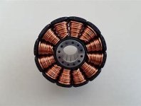
I really like the separated tooth winding, always wondered why it's not done like that. Simple,easy to wind, high fill factor, less risk for shorts.
I think some flux is lost in the divisions but i don't know how much, miles looked at it back in his motor design days.