Getting started with Field-Oriented Control

Joined
May 20, 2019
Messages
38
I want to get started with customizable FOC for a 36V/500W front hub motor (Q100 type). My goal is working traction control and I'm leaning towards monitoring the "speed observer" in an FOC algorithm and reducing the torque when acceleration is high. What is a good system that would allow me to focus on software and physics with minimal soldering?

For $104 total, I'm close to pulling the trigger on the Texas Instruments eval boards LAUNCHXL-F280069M (CPU) and BOOSTXL-DRV8323RS (54V, 15A power stage). Having worked with TI MCUs elsewhere, I'm weary of the mess they've made on the software and documentation side. VESC 4 controllers are available for a similar price, but jumping into the VESC code looks like a deeper pool than TI, which has various "lab" modules to teach about their FOC library.

FOC Development Boards were discussed years ago with TI getting the most attention, but I wonder if anyone has recent experience, as this area of technology has matured (or at least become more accessible)?
 
I've developed an open source firmware for Lishui-Controllers with STM32 processors. It has sensorless control implemented already. The oberserver algorithm is adapted from the VESC.
The controllers are available at several internet-shops or directly from China

The sensorless-branch can be found here:
https://github.com/stancecoke/LishuiFOC/tree/Sensorless_VESC

In the readme you can find several useful links for getting started with FOC.

regards
stancecoke
 
To do proper traction control you would probably need a reference for the vehicle's actual ground speed and / or actual acceleration. Just limiting the spin up rate won't necessarily do what you want since different surfaces (and different approaches to gripping them) give you a very wide range of traction and you would have to err on the side of a very slow spinup to encompass all of them which would suck.

Electronic traction control sucks in general though and I would discourage it. It's way better to learn that through your wrist, eyes, vestibular system etc. You will become a much better rider and have a blast. And ditch the idea of a front wheel motor. It puts your grip where you have less of it when you accelerate and of course you can't wheelie which is one of the best things to do on 2 wheels (except maybe in reverse).
 
flat tire: The driving wheels can't be changed so easily on this vehicle. I'm interested whether you're writing from first hand knowledge of the engineering issues associated with traction control, or general expectations? Supposedly, traction control (TC) can be more effective for electric vehicles than conventional ones.

The ABS and TC performance of full electric vehicles can
be enhanced due to higher frequency (above 10 Hz) of wheel
torque modulation as compared with conventional ABS/TC
having average operational frequency up to 3...10 Hz.
From https://doi.org/10.1109/TVT.2014.2361860.
 
ProgramThyself said:
That is an interesting option. Thanks, stancecoke. Do you know the eRPM limit?
https://translate.google.de/translate?hl=&sl=auto&tl=en&u=https%3A%2F%2Fwww.pedelecforum.de%2Fforum%2Findex.php%3Fthreads%2Fopen-source-firmware-f%C3%BCr-lishui-controller.61113%2Fpage-10%23post-1299807

I get a maximum of 24000 eRPM in sensorless mode.

regards
stancecoke
 
After about 3 weeks with the BOOSTXL-DRV8323RS and LAUNCHXL-F28069M boards, TI's automatic parameter estimation and instaSPIN-FOC are finally working. InstaSPIN indeed...

If anyone else uses these boards, it is critical to add capacitors C9-11 of about 100 nF to the BOOSTXL for parameter estimation to work. The board ships with those placements empty, which is mentioned (between Windows screenshots) in the BOOSTXL's Quick Start Guide (but not the User Guide). The capacitors filter the driver's output voltages across multiple PWM cycles for ADC measurement.
 
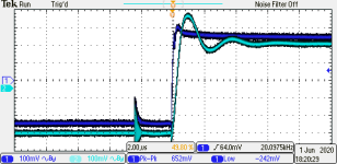
On the BOOSTXL-DRV8323R, capacitors C14-16 (2.2 nF) should also be removed. They are parts of RC filters intended to quiet the output of the three current sense amplifiers (CSA). But they introduce ringing, without improving the dispersion of ADC measurements. The 12 bit ADC standard deviation is always about 2.5 LSB. On the attached scope trace with CSA gain of 10, channel 1 has C14 removed, while channel 2 still has C15 in place.
192321_TEK.png
 
What is the implication/effect of the ringing in the performance of the control ? Does removal of the capacitors have a practical effect ? There doesn't appear to be any significant filtering being performed by those capacitors, but the slight lag is apparent. Wonder why they were added in the first place. Interesting.
 
At maximum PWM duty cycle, the low period (when the ADC measurements occur) vanishes, and FOC stops working. There seems to be a trade off between keeping duty cycle below 100 % (so FOC can get its ADC readings to function) and maximum speed (which needs 100 % duty cycle). Eliminating the ringing allows FOC to receive accurate inputs at 97 % duty cycle. But I have not seen an improvement in wheel speed or current consumption, so the benefit may be theoretical.

A minor practical improvement is in reconstructing the battery current, which is not measured on the BOOSTXL-DRV8323R. It can be calculated as Ibat = Ia * fa + Ib * fb + Ic * fc where Ix and fx are phase current and on-fraction for phase x. Accurate ADC readings improve this calculation.
 
cross fertilization https://endless-sphere.com/forums/viewtopic.php?f=30&t=105139
 
ProgramThyself said:
A minor practical improvement is in reconstructing the battery current, which is not measured on the BOOSTXL-DRV8323R. It can be calculated as Ibat = Ia * fa + Ib * fb + Ic * fc where Ix and fx are phase current and on-fraction for phase x. Accurate ADC readings improve this calculation.
Very interesting.

Does having 3 phase currents measured (as opposed to 2 in some controllers) make this more accurate or just easier? Is there an option to connect an external current sensor to measure the battery current directly?
 
Another question(s), sorry.

Are the Clarke and Park transforms calculated in realtime ? i.e. PWM off -> ADC -> P/C transforms -> PWM on. From what I can understand about clock timing in the InstaSPIN guide, ideally that's how it works, but I'm not totally sure I'm interpreting it correctly. Or what happens if the PWM period is shorter than the InstaSPIN execution ? Then it starts talking about FAST and I'm totally lost.

And WRT field weakening, what is the criteria that decides when the field weakening will "engage" ?

Sorry if these questions are a bit "simple". The InstaSPIN users guide is 574 pages, and most of it is over my head atm. I'm amazed you can get something up and running in 3 weeks. It'll take me a year to get through the manual, and still not understand >5%.
 
Sam:

Battery current reconstruction should also work with 2 ADC current readings, but my board gives 3 so that's what I use.

The processor is a DSP with deterministic timing. It operates at 20 kHz PWM. Every 2 PWM cycles (10 kHz), new ADC readings arrive and DSP calculations update the PWM duty cycle. That is the highest priority task and the 1:2 ratio is adjustable at compile time. Lower priority work goes on in the background (UART, display updates, SD logging).

FAST is TI's acronym for their proprietary motor-angle (and speed/torque/flux) estimator, which also updates with each set of ADC readings. The angle is important to know for FOC and seems to be the subject of much magic-sauce cooking. But my motor has Hall sensors for low-speed angle estimation (which is the hardest), and high-speed estimation, when there are large induced voltages, is not rocket science. So as a beginner who is learning about the technology, I am focusing on FOC.

For now, field-weakening is based on TI's "lab09a". Whenever the output voltage (vector length) exceeds a threshold, the field-weakening current is incremented up to a maximum. This current is decremented when output voltage is below the threshold.

It was 3 weeks to get things spinning initially, followed by a break of about 5 months because I was annoyed with TI's shoddy development boards, support, and apparent general decline. Now I'm getting back into it. Their labs guide (version 1.0.16) and examples included with MotorWare http://www.ti.com/tool/MOTORWARE helped me a lot (note that newer versions of the TI labs guide are missing important examples). But there were a lot of gotchas, perhaps due to my combination of processing and driver boards.

I agree that the volume of documentation is overwhelming. Rather than reading through everything, which is impossible, I started with simple steps and rewrote/shortened TI's example code to clean it up. Then, when something didn't work or I needed more info, I referred to the docs. Still, these boards are only in a test stand now and another month or two will be needed before they can drive a vehicle.

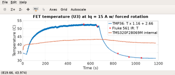
Update: Power handling and thermal envelope are my biggest concern now, and I plan to glue a sensor to the PCB under the FETs. I also plan to add RC snubbers, which are recommended by the FET datasheet https://www.ti.com/product/CSD88599Q5DC. Beyond that, the remaining work for vehicle use is systems integration.
 
Thanks for the explanations. Much appreciated. That all makes sense, and filled in a lot of gaps for me.

I guess different implementations of FOC may have varying methods of accomplishing each task (rate of PWM update, field weakening phase-in, etc), but your explanations is a good point of reference. Thanks.
 
Continuing the driver temperature measurement that I described elsewhere:
https://endless-sphere.com/forums/viewtopic.php?f=2&t=106878
A modest fan directed at the top of the driver board helped a lot, and the temperature rise over ambient decreased from 69 to 28 C. The PCB could also be clamped to metal from the enclosure (to be designed). Maybe there is still hope to get to 35 A. I'm also unsure about the different conventions for the Id, Iq normalization that might change the current requirement by a sqrt(2/3) factor.
https://en.wikipedia.org/wiki/Alpha–beta_transformation
 

Attachments

  • Screenshot from 2020-06-27 19-13-39.png
    Screenshot from 2020-06-27 19-13-39.png
    19.1 KB · Views: 1,088
Back
Top