Controller MOSFET replacement

newb123

100 W
Joined
Jun 7, 2019
Messages
102
The inside of my controller got wet, and after testing the MOSFETS with the DMM, I found 2 of them to be shorted out.
The ID # on them are F101DE IR 251H 2D 71
I cannot find any spec sheet or replacement.
These are driven by gate drivers, not logic level driven, so I would need that type of replacement
Does anyone know of a compatible model, that is common in controllers?
 
I have an old Chinese 400W controller

It has 6 IRF 3205 225X mosfets, one is blown so I would like to replace all

So after looking at the data sheet and testing with a diode checker from S to D and getting a .500 drop, it seems they are all N type mosfets

Is this correct? I thought the controller had 3 N channels and 3 P channels

If I replace all 6 with new 3205s will that work?
 
There are 3 phases that need to be pulsed.

Three have a : low side.... and three have a high side.... So that is two ( transistors in a 6 fet) for each color... ( blue yellow green) for 6 total.. and if they all are the N-Channel OEM installed, replace with all N-Channel.

N-Channel MOSFET are always used on both High and Low side on BLDC applications.

"More efficient, more available and cheaper."

Easier to design the gate drivers.

Random quotes from round the web:
"Use of N-channel FETs isn't exclusive. The gate drive is simpler at low voltages (below 15V or so) if you use PMOS on the top side; if your current needs are also modest it may be cost effective to use the more expensive pass transistors so that you can use simpler gate drive circuitry."

"PMOS requires extra high side gate circuitry anyways above ~20V (limited by max |Vgs| that the gate-source is exposed to when gate pulled to GND to turn it on in a simple PMOS high side gate drive scheme) so you don't save any effort. Max |Vds| is higher so is not the weakest link in a simple high side PMOS scheme. If you need high side gate drivers anyways then you might as well just use NMOS."
 

Attachments

  • Nchannel.jpg
    Nchannel.jpg
    41.5 KB · Views: 895
Thanks very much for the reply and detalis.

So how does that work; a halls senses where one top coil is at, fires one top and bottom pair of N mosfets, current flows through the mosfets to the top coil, then through the bottom mosfet, then through the bottom coil? Why have one high, one low? So that rotor chases a field? How can you have a gate driver turn on a mosfet high, and have another go low? I mean, whats the meaning of state "low"? It seems to imply its off.

Thats why I was confused, I thought one set was P and the other N channel mosfets.
 
awhile ago, my controller got wet, powered it up, then blew the fuse from the battery (30 AMP). some mosfets were blown

I tested and replaced all the 3508 mosfets. there were some resistors on the board measuring 0 ohms. I dont know what they are used for. The gate surface mount resistors were at about 20k, I guess those are pull down resistors.

Upon power in the controller, immediately I blew the 30 AMP fuse, again. I tested all the mosfets; about .500 on the diode checker D to S and S to D, so I guess they are blown.

What could go bad in a controller so short out everything? I replaced the 50 V 220 uF cap, and Fairchiled 130005 power regulator (switching transistor?) 3 lead chip

Phase wires seem normal- free spin with no phases shorted, resistance with each phase shorted. no phase to ground readings, all OL on the meter

I havent checked the motor or throttle halls, but that doesnt seem to be a source of a dead short upon start up

---------------------------------------------------------------------------------------------------------------------------------------------------

UPDATE TO THE ABOVE:

Its not the motor phase wires or halls throttle and motor leads. I put the battery on the controller, with all peripheral wires disconnected. Immediate the fuse was blown. I dont know where in the controller this might be happening.

So the current enters directly to the top (Drain) of the 3 top mosfets, then from there, through a phase winding according to a halls reading, then back to the bottom of one of the drain to source mosfets?

But with the phase wires disconnected, some current is just shooting through, it seems from top mosfet to bottom.

On my controller, the pos supply comes directly in to the top of a heavy solder trace to the 3 mosfets then off the source of the 3 bottom mosfets, another heavy solder trace on the bottom of the board

Testing ohms between the pos and negative heavy solder traces, I get about .500K

Dont know if that is normal but seems I have another blown mosfet?
 
Most likely the gate drivers for at least one of the phases (possibly all of them) have failed, probably damaged by the FETs themselves when those first failed.

If the gate drivers are stuck on, then they leave the FETs on, which then causes shoot thru which then detroys the FETs again.

The gate drivers are usually all SMT parts, inclduing the resistors and capacitors associated with them (which can also be damaged), and this usually makes the controller not repairable, or at least not worth doing.

To test the drivers you'd leave the FETs off (so they aren't destroyed again and don't blow the fuse), and test for the correct output signals on the gate pin of the FET pad/trace, for all the hall combinations as you manually turn the wheel. (with motor connected to the controller, and controller connected to battery and turned on, and using just a tiny bit of throttle to cause the controller to try to turn the gates on).
 
Yes that makes sense because most of the mosfets were once again blown, so the drivers must be defaulting to on or high to the gates. I was thinking mosfet shoot through also, but could not figure out why they would default to ON.

I cant test the drivers because upon connecting up to the battery, no throttle, I blow the fuse.....oops didnt read this..thanks for that

To test the drivers you'd leave the FETs off (so they aren't destroyed again and don't blow the fuse), and test for the correct output signals on the gate pin of the FET pad/trace, for all the hall combinations as you manually turn the wheel. (with motor connected to the controller, and controller connected to battery and turned on, and using just a tiny bit of throttle to cause the controller to try to turn the gates on).
I just ordered a cheap chinese made controller, the generic type with all the wires coming out; hopefully it will be
an easy connect with phase wires, halls wires and power switch

I noticed on the blown board that there were about 5 resistors from the halls sensor and power/ground wire connections, I assume those are pull ups but cant trace to where they go next. are those signal wires going back to the micro controller? was thinking about cutting that part of the board out, and putting in some leds after the pull ups and a 9V battery to make a halls tester

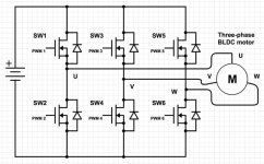
looking up my gate drivers they were IR 2101S. I understand how the top mosfet can be turned on with the HO driver out put but how can the bottom mosfet be turned on with a LO driver out put? It means, the bottom mosfet is at a lower potential, than the top in order for the current to flow to its source or ground? it seems that both N channel mosfets would require the same gate voltage to turn on. There are only 3 drivers so it means each driver is controlling a pair of N channel mosfets.

ir2101 gate driver.jpg

Oh, I think I see. The top mosfets gate must be higher than its source, since the bottom mosfets source is at ground, but I still dont see how the top mosfet gets turned on, if the bottom is off, without a path to ground, for the top mosfet.
 
Back
Top