Homopolar Switched Reluctance Motor

Username1

100 W
Joined
Nov 26, 2013
Messages
168
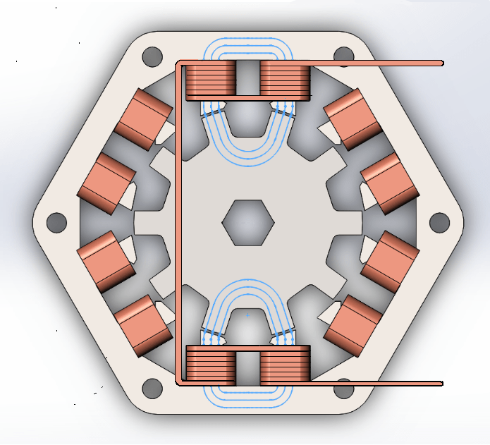
I found this paper about an interesting type of motor. https://fdocuments.in/document/a-new-two-phase-homopolar-switched-reluctance-motor-for-electric-vehicle-applications.html They actually researched it specifically for electric vehicles like ebikes and escooters.

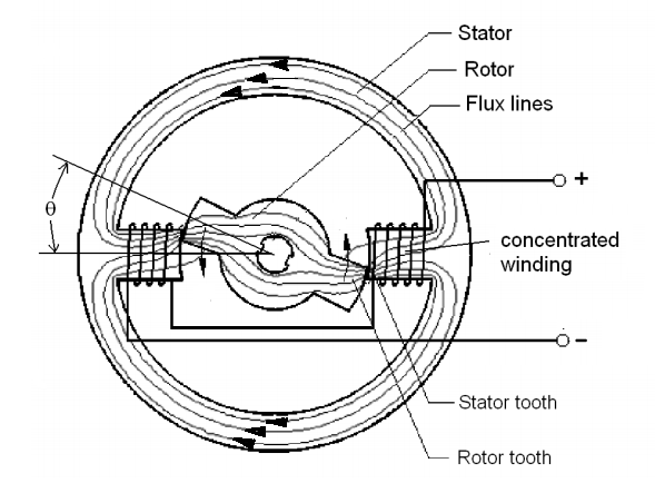
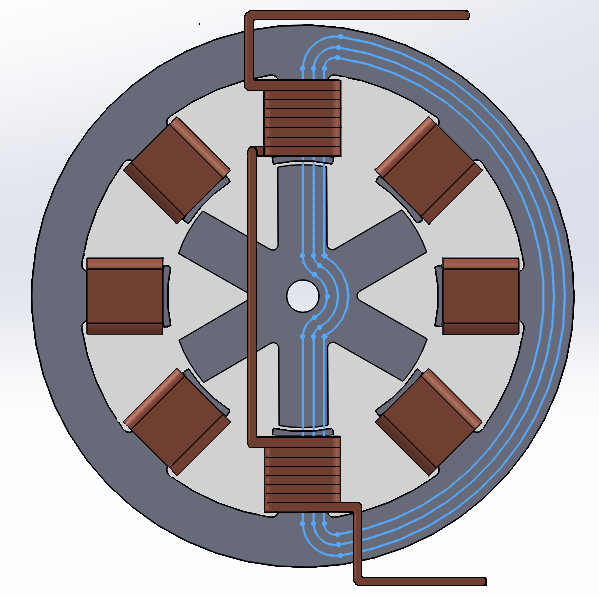
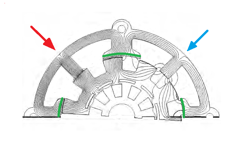
It has some interesting features. It's a switched reluctance hub motor with an axial flux design (pancake motor), but the flux does a 90 degree turn, meaning it has a radial rotor. The motor is inherently single phase and homopolar, meaning it only uses one winding. In the paper, they stack 2 side by side (and add a stepped air gap) for the purpose of self starting.

I would argue a single phase version is more interesting as it's even simpler, and i personally don't see the need for self starting on ebikes or electric kick scooters. It seems easy enough to give a pedal or kick before taking off, and most scooters already deliberately add this as a safety feature.

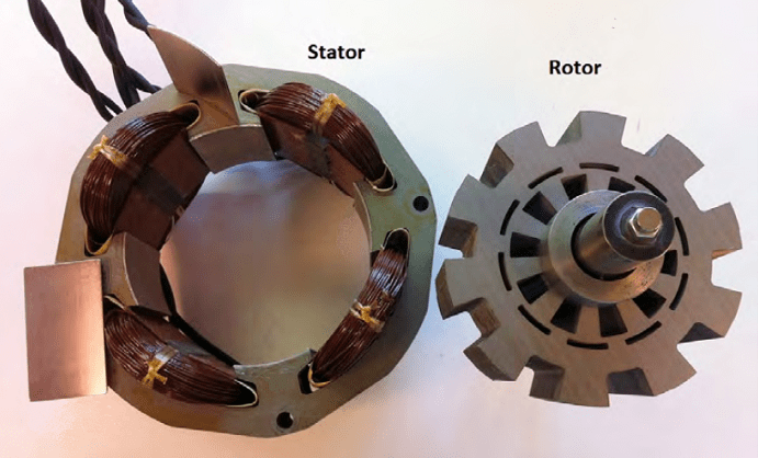
It seems like an extremely simple and durable design. Being switched reluctance, it has no magnets or conductors in the rotor, meaning the rotor can't overheat. Another benefit of switched reluctance is no drag when coasting/turned off, which is a great plus. With the simple rotor and single winding per phase, it looks way easier to build. I'm not sure how it compares on power density but thought it was a very clever design. What do you think?
 
This is the actual article:

https://docs.google.com/viewerng/viewer?url=https://fdocuments.in/google-reader?url%3Db7a8e6a325f4660da7bd73e2a412f1257fefb1c040e1cdff05e2cec31990cd223316d544005c9dea2a0914bfa94c69b84fd1f5549bd30fbdbda33331811d36ebj28uBnSKI9RFrr4WS4NWzApPwBOA4BwfXp+rq/bw2HD6fx4rrS/vUQBgwfEaPy8U3pKWWR6O1MIC2VbeltE5Soa/7L0kk+/2bA4ealdgUDTMIDjwj3W3UZ3O7xb+NsWvcTfHP5v+oon8sHkaXrabO9oRCxrz3eET8Qv3UGuGfuY%3D

I skimmed and didn't read the whole thing. This motor design appears to be an induction motor. Typically, they have the armature inside the stator, like an inrunner. This design is the opposite. The armature spins around the stator, like an outrunner.

This motor induces a magnetic field from the winding into the armature...like most induction motors do. In that regard, the motor will last as long as the windings can last. Bearing failures and winding failures IMHO are the things that will stop it from running more or less forever.

A few general thoughts about this motor design...
1. Since it is an induction motor, the induced magnetic field is very short lived and will only be as strong as the induction effect can create. This will limit torque density. I have no idea if the induced magnetic field is as strong as that of an N35 neo which are common in BLDC motors.
2. Induction motors generally need make some RPM's to be effective. They don't do well at near stalled states...unlike a BLDC motor which pulls pretty well even stalled.
3. It is an AC sine wave motor that uses the rotation of the sine wave to create commutation. Speed for any motor that uses this, is usually controlled by adjusting the frequency of the sine wave. Turning down the voltage also works, but less well.
4. You really want at least 2 phases. Self starting is an important characteristic. I think you will find people only kick off or pedal because they have no other choice. I personally build in such a way that my EV's will take off all on the motors power only. So then...2 phases...not really that much less complex than 3 phases like in a BLDC motor.
5. This article was published in 2003. If the design hasn't grabbed hold by now there's probably really good reasons. By contrast, BLDC has definitely taken over the EV world.
 
Not sure what you mean by "actual article". I linked the full scientific paper discussing this motor with all the info included. Clicking your link brings up a blank page for me. But it's definitely not an induction motor, it's a switched reluctance motor (says so right in the paper's title).

As for the self starting, i personally don't see it as necessary but that's just my opinion. You only need to be going like 1km/h. The upside is the motor would become even simpler with only 1 phase/winding. Regardless, this motor is capable of self starting with 2 phases and a stepped air gap like in their example.
 
Username1 said:
Not sure what you mean by "actual article". I linked the full scientific paper discussing this motor with all the info included. Clicking your link brings up a blank page for me. But it's definitely not an induction motor, it's a switched reluctance motor (says so right in the paper's title).

As for the self starting, i personally don't see it as necessary but that's just my opinion. You only need to be going like 1km/h. The upside is the motor would become even simpler with only 1 phase/winding. Regardless, this motor is capable of self starting with 2 phases and a stepped air gap like in their example.

Sadly its becoming more and more necessary to ignore EG. All too often he just reads 2 lines and assumes the rest (this is not the first time by any means), ending in the above post attempting to 'correct' you, because he somehow thinks your talking about induction motors despite the clear OP talking about a completely different motor type, and then providing information thats incorrect anyway (ie low starting torque of induction motors - something thats only true for some induction motors, and then only if operating from a fixed frequency source, ie not a vehicle where VFDs are the norm). Moreover my pointing this out will be taken as a personal insult and as being completely off topic, rather than an attempt (not the first) to help out and point to where he's going wrong. I honestly dont know how he manages it... but anyway:

Taking the novel aspect of the construction as a given, im not seeing a huge benefit here (though I have to state I'm not a motor expert so I could easily be missing the forest for the trees). Its cheaper to build for sure... as easy as winding wire on to a drum, but I gotta think that the flux path (and resultant leakage) is going to result in a lower overall efficiency compared to more conventional winding configurations. So you save money on the motor, but end up needing to spend more on the battery to compensate for the lost range, and a bigger controller to compensate for the lost torque. Perhaps the efficiency hit isn't too bad and so it'll not require notable changes to other components, but the lack of any discussion/testing on that subject in the paper makes me wonder...

Being 2 pole too makes me think of torque ripple too, something thats a common issue with SRMS, so its likely to be a noisy motor too? particularly when its so easy to add a 3rd (or more) phase to the motor to smooth it out, just copy paste a single phase in parallel, seems they are sticking with a 2ph configuration to highlight its uniqueness, rather than going for multiple phases and focusing only on the simplified manufacturing...

Unipolar controller is a neat aspect though, essentially just 2 buck converters in parallel, simple as. The configuration of the stator also means flat/square copper could be used, meaning near on 100% copper fill should be easily achievable. Could also use anodized aluminium to save a few more $ and further improve fill? I seem to recall seeing a aluminium wound induction motor somewhere here on ES, where the lack of need for enamel on the windings helped improve conductor fill factor.

Hopefully one of the motor guru's on ES can comment on what im overlooking here?
 
sn0wchyld said:
Taking the novel aspect of the construction as a given, im not seeing a huge benefit here (though I have to state I'm not a motor expert so I could easily be missing the forest for the trees).

One HUGE benefit i see is 0 drag when not powered (applies to SR and induction motors in general). With things like ebikes and electric kick scooters, for me the drag of BLDC motors renders them totally garbage when human powered. Nobody wants to pedal or kick and feel like the brake is dragging. People often mention motor efficiency, but human powered efficiency matters even more. Even when using power to get up to speed, the feeling of freely coasting is something i miss with BLDC. Gives the ride a totally different feel.

Overall i'd say the benefits would be no drag, extremely simple/cheap design, and very rugged. Perhaps also a simplified controller like you mentioned. It seems to me like sending pure dc on/off to a single coil (single phase or multiphase) may be much simpler. Maybe a simple on/off would be too jarring, and would require ramping the current up and down or something, making it more complicated. I'm very uneducated on how controllers work so i can't say.

sn0wchyld said:
... but I gotta think that the flux path (and resultant leakage) is going to result in a lower overall efficiency compared to more conventional winding configurations.

To continue my earlier point, i'd argue that there are very significant energy savings with a motor that freely coasts. I know from experience with escooters, that even fairly steep hills do little to maintain much speed, resulting in using the throttle during almost the entire trip regardless of hills (or lack of). If you're able to coast on flat ground and going down hills, that's a massive savings. Especially considering that regen in it's current state is pretty pathetic in the 5% range if your motor/controller even use it.

About this design specifically... The flux path does have that unconventional 90 degree turn. I'm guessing this is where you see the potential problem. Is it the case that a sharp turn causes high losses? That seems like it could be true, especially considering i always hear talk of short (and probably direct) flux paths being desirable. One the other hand, i noticed that unlike conventional switched reluctance motors, the flux path through the rotor is EXTREMELY short. The rotor teeth are basically glued onto a nonmagnetic backing (almost exactly like magnets on a BLCD), so the flux is literally just passing through the teeth. Not sure either how it would compare overall to other SRM or BLDC.

sn0wchyld said:
Being 2 pole too makes me think of torque ripple too, something thats a common issue with SRMS, so its likely to be a noisy motor too? particularly when its so easy to add a 3rd (or more) phase to the motor to smooth it out, just copy paste a single phase in parallel

I'm wondering, why would adding more phases inherently smooth out the motor? Is it strictly about number of pulses per rotation? Because if that were the case, you could simply use 1 phase with more poles. For example 1 phase with 18 poles, vs 3 phase with 6 poles each. Or is it because using 3+ phases has some kind of overlapping, meaning more than 1 phase is active at a time for some duration of time?
 
Username1 said:
sn0wchyld said:
Taking the novel aspect of the construction as a given, im not seeing a huge benefit here (though I have to state I'm not a motor expert so I could easily be missing the forest for the trees).

One HUGE benefit i see is 0 drag when not powered (applies to SR and induction motors in general). With things like ebikes and electric kick scooters, for me the drag of BLDC motors renders them totally garbage when human powered. Nobody wants to pedal or kick and feel like the brake is dragging. People often mention motor efficiency, but human powered efficiency matters even more. Even when using power to get up to speed, the feeling of freely coasting is something i miss with BLDC. Gives the ride a totally different feel.


Overall i'd say the benefits would be no drag, extremely simple/cheap design, and very rugged. Perhaps also a simplified controller like you mentioned. It seems to me like sending pure dc on/off to a single coil (single phase or multiphase) may be much simpler. Maybe a simple on/off would be too jarring, and would require ramping the current up and down or something, making it more complicated. I'm very uneducated on how controllers work so i can't say.

sn0wchyld said:
... but I gotta think that the flux path (and resultant leakage) is going to result in a lower overall efficiency compared to more conventional winding configurations.

To continue my earlier point, i'd argue that there are very significant energy savings with a motor that freely coasts. I know from experience with escooters, that even fairly steep hills do little to maintain much speed, resulting in using the throttle during almost the entire trip regardless of hills (or lack of). If you're able to coast on flat ground and going down hills, that's a massive savings. Especially considering that regen in it's current state is pretty pathetic in the 5% range if your motor/controller even use it.


About this design specifically... The flux path does have that unconventional 90 degree turn. I'm guessing this is where you see the potential problem. Is it the case that a sharp turn causes high losses? That seems like it could be true, especially considering i always hear talk of short (and probably direct) flux paths being desirable. One the other hand, i noticed that unlike conventional switched reluctance motors, the flux path through the rotor is EXTREMELY short. The rotor teeth are basically glued onto a nonmagnetic backing (almost exactly like magnets on a BLCD), so the flux is literally just passing through the teeth. Not sure either how it would compare overall to other SRM or BLDC.

sn0wchyld said:
Being 2 pole too makes me think of torque ripple too, something thats a common issue with SRMS, so its likely to be a noisy motor too? particularly when its so easy to add a 3rd (or more) phase to the motor to smooth it out, just copy paste a single phase in parallel

I'm wondering, why would adding more phases inherently smooth out the motor? Is it strictly about number of pulses per rotation? Because if that were the case, you could simply use 1 phase with more poles. For example 1 phase with 18 poles, vs 3 phase with 6 poles each. Or is it because using 3+ phases has some kind of overlapping, meaning more than 1 phase is active at a time for some duration of time?

RE drag - a well built PM motor can have low drag too (though yea never gonna be the same as SR), ive had 1 hub in particular that almost felt like it wasn't there - drag is down to iron losses, so thin lams and low pole counts can make for a motor that spins very freely, even as a hub motor. Alternatively, a clutch or freewheel will achieve the same thing... but yea, SR are gonna win out in most cases, as thin lams cost $ and clutches cost $ and mech complexity...

This benefit however is not unieque to THIS motor... that's what I meant by the 'i dont see much benefit here' statement (though I see how that could have been seen as a judgement on all SRMs).


I pretty much agree, other than the point of noise and efficiency. The controller 'brain' would help to smooth out from a strait out 'on off' type control, but that wouldn't be too hard anyway (modern controllers do this already to a very high degree of control)


See above... agreed that some motors can have notable drag, but a well designed on can be surprisingly good at freewheeling. For skateboards etc though having true 0 drag would definatlye be a + in favor of a SRM.


Yep, pretty much. May not be too bad as mentioned, but the lack of examination on efficiency (granted this is a proof of concept not a fully fleshed out design) makes me wonder - particularly the 'decoupling' between each of the 2 phases.


basically yes, you could achieve it by adding more teeth too. the bigger the 'step' between each tooth the bigger the ripple. There's several ways to improve it but adding a 3rd phase would be very easy. only issue with higher teeth is the need for higher switching frequencies and how that might be limited by the inductance of the coil (though this probably wont be a big limiter im guessing)


Again though im no expert either... so take all this with a grain or two of salt. Could be its a good idea for a new motor design, mainly I just see some potential issues that were (conveniently or otherwise) left out of the analysis.
 
@sn0wchyld I guess i was not only comparing this specific configuration to others SRMs, but also pointing out the benifits of SRMs in general compared to BLDC motors which have a monopoly in small EVs. When talking strictly about this specific design over a normal SRM, it seems we both agree that it's extra simple construction would be the main benefit.

On the topic of noise, i remember hearing that almost all the noise in SRMs comes from the rotor. A normal SRM rotor (both inrunner and outrunner) is a complete ring with teeth, made of laminated steel. I believe in this design, only the teeth themselves are steel, and are totally separate from each other. I wonder if this could contribute to a quieter motor.
 
Username1 said:
One HUGE benefit i see is 0 drag when not powered (applies to SR and induction motors in general). With things like ebikes and electric kick scooters, for me the drag of BLDC motors renders them totally garbage when human powered. Nobody wants to pedal or kick and feel like the brake is dragging.
Keep in mind that what you are feeling with a PM motor is primarily cogging, not drag. They are very different. You do lose some energy to eddy current losses, but they are tiny compared to cogging forces (and cogging forces do NOT slow you down once you are at speed, since they cog in both directions.) It just feels funny.
I'm wondering, why would adding more phases inherently smooth out the motor? Is it strictly about number of pulses per rotation?[/b] Because if that were the case, you could simply use 1 phase with more poles. For example 1 phase with 18 poles, vs 3 phase with 6 poles each. Or is it because using 3+ phases has some kind of overlapping, meaning more than 1 phase is active at a time for some duration of time?
You need at least 3 phases to guarantee a start. With one phase, it is quite easy to get the rotor into a position where there is net zero force acting on the rotor, and thus it will not start unless you move the rotor - and even then it's easy for it to "kick" back into a position where there is no torque. With two phases this is greatly reduced, and with three phases you can guarantee that you can always start the motor.

Once you have three phases, you can use a square wave drive, but that generates a lot of torque pulsation as the new phase "engages" and the old one "disengages." More phases helps smooth this out (like on the Tidalforce and EMS motors.) However, sine wave drive is now simple and cheap to do and this avoids the problem entirely.
 
@billvon The way i understand it (I could be wrong here), "drag" happens when the magnets pass by the iron stator poles while the motor is off. Because iron is attracted to both negative and positive magnetic fields, there is no counteractive force. This attraction simply causes "drag" when near either side.

I understand that you need 3 phases for 100% reliable self starting. My point was simply that i don't think it's necessary on things like ebikes or escooters where you can start moving yourself using human power. The benefit being you get a simpler motor using only 1 phase. It's somewhat relevant here because unlike normal motors, this one is inherently 1 phase, where you must stack copies side by side to add more phases.
 
Switched Reluctance motors already exist. They are used as the front motor on the AWD Tesla EVs, and Tesla has hinted that they may expand their use to other applications.

A key desirable feature is the lack of rare-earth permanent magnets, which could soon prove to be a bottleneck to expanding production. In the pic below, the rotor and also the stator-core are made from a stack of laminated steel. The only other material shown in the graphic is the copper in the wire (meaning there are no neodymium magnets).

MotorSR26.png


In this subject, the word homopolar simply means that the poles are never tasked with alternating the direction of the magnetic flux. Common electric bike hubmotor designs often alternate the direction of flux for each coil in the stator. The permanent magnets in an ebike rotor (of course) only have their magnetic flux pointed in one direction, and they are fixed in their place on the rotor.

The electromagnetic coils in the ebike-stator can have the current direction alternated by the controller, so the magnetic flux direction also reverses. In this way, the coil may pull at a permanent magnet that is near it, and then a moment later it can push on that same magnet...if desired. Flux reversals like this cause more eddy current heat than if the flux is only flowing in one direction, as the coil is turned on and off. Below is another graphic I found useful.

MotorSR20-1.png


Below is a FEMM analysis of an existing SR homopolar motor with 2 phases (red phase / blue phase). In this graphic, the red phase is energized. The thin green lines are weak high-temp ferrite magnets, which add no power. They are flux guides and they also reduce torque-ripple (they look odd because they are coated).

MotorSR22.png


MotorSR23.png


Here's a 3-phase proposal below. It's production status is unknown.

MotorSR8.png


The patent in the first post and title is for an SR axial-flux stator, with radial airgap (all the SR motors pictured above are simple common radial-flux). It specifically states that a conventional SR motor used as a hubmotor is constrained in its power-producing mass, and switching to the axial configuration would allow it to dramatically increase the copper mass inside a normally sized wheel.

I can see this being very useful in a forklift or a golf cart, which is quite a large market. It still requires copper and steel, but no neodymium. Because they contain no neodymium, they generate less heat (permanent magnets are typically not laminated, and often have their own eddy currents), and they also can withstand more heat than a motor that does have neodymium magnets, which typically start losing their magnetism around 200F (dependant on grade)

The OP's motor can be thought of as two side-by-side one-phase axial-flux motors, with two stators in the center, and the rotors are radial. Since the rotor poles are wider than the air gaps between those poles, there is pole overlap when using only two rotors/stators if they are equally offset.

They state that 3 phases would be needed to be reversable, so this proposal is a uni-directional 2-phase motor. They claim it is self-starting. By having only two phases, they now have the option of using an axial configuration, which then allows a higher copper mass per motor volume, compared to a conventional radial-flux SR motor inside the same-size of wheel.
 
@spinningmotors Just one thing you may have missed, is that this is not a conventional axial flux motor with axial (side) rotors poles. The rotor poles are actually radial (right in the middle of the stator). Easy to miss as this is a very unique design.
 
Username1 said:
@billvon The way i understand it (I could be wrong here), "drag" happens when the magnets pass by the iron stator poles while the motor is off. Because iron is attracted to both negative and positive magnetic fields, there is no counteractive force. This attraction simply causes "drag" when near either side.
Sort of. But when the iron is closing in on the magnets, there is a force that is advancing the wheel. When the iron is receding from the magnets, there is a force retarding the wheel. These make you feel a torque ripple, but the NET (average) torque over time is zero.

However, as the magnetic fields increase and decrease in the iron of the stator (or rotor depending on motor construction) there are small currents generated due to Faraday's Law in the metal itself. These dissipate quickly due to the resistance of the metal and turn into heat. These losses represent the "drag" that wastes energy, specifically by converting motion into magnetic fields into electric current and finally into heat.

(That's also why SR motors are less draggy; almost no magnetic fields to generate those eddy currents.)
I understand that you need 3 phases for 100% reliable self starting. My point was simply that i don't think it's necessary on things like ebikes or escooters where you can start moving yourself using human power. The benefit being you get a simpler motor using only 1 phase. It's somewhat relevant here because unlike normal motors, this one is inherently 1 phase, where you must stack copies side by side to add more phases.
Yes, if you can get it to a sufficient speed, then even a one phase motor will work OK. However keep in mind that an SR motor does not have inherent magnetic fields, and so can only drive through half the phase (when the salient pole is closing in on the driven inductor.) So torque ripple will be high, and you'd want to choose a starting speed/# of poles to minimize that.
 
billvon said:
Sort of. But when the iron is closing in on the magnets, there is a force that is advancing the wheel. When the iron is receding from the magnets, there is a force retarding the wheel. These make you feel a torque ripple, but the NET (average) torque over time is zero.

However, as the magnetic fields increase and decrease in the iron of the stator (or rotor depending on motor construction) there are small currents generated due to Faraday's Law in the metal itself. These dissipate quickly due to the resistance of the metal and turn into heat. These losses represent the "drag" that wastes energy, specifically by converting motion into magnetic fields into electric current and finally into heat.

Ah that makes perfect sense thanks for explaining that. I was for some reason missing the part where going towards the pole aids you. Seems obvious now that you explained it. The actual magnetic forces even out, and the losses are coming from induced currents as you say.
 
sn0wchyld said:
Being 2 pole too makes me think of torque ripple too, something thats a common issue with SRMS, so its likely to be a noisy motor too? particularly when its so easy to add a 3rd (or more) phase to the motor to smooth it out, just copy paste a single phase in parallel, seems they are sticking with a 2ph configuration to highlight its uniqueness, rather than going for multiple phases and focusing only on the simplified manufacturing...

It does seem odd they avoided using 3 phase. Maybe heat is part of the reason? The middle stator would be sandwiched between the other two, so it should operate hotter.

sn0wchyld said:
The configuration of the stator also means flat/square copper could be used, meaning near on 100% copper fill should be easily achievable. Could also use anodized aluminium to save a few more $ and further improve fill? I seem to recall seeing a aluminium wound induction motor somewhere here on ES, where the lack of need for enamel on the windings helped improve conductor fill factor.

The idea of using flat bars is really cool. For each phase, you could wind a single bar the entire width of the stator and simply choose the thickness based on how many turns you want.

Didn't know you could replace enamel with anodizing on aluminum, very interesting. Winding a single aluminum bar (per phase) seems like a great way to reduce costs and simplify the design even further.
 
https://anofol.de/en/products/anodised-aluminium-strips-and-foils/

Here's a company i found that makes anodized aluminum strips for electrical purposes like this. Their website has lots of information about the claimed advantages. If you scroll down, their technical details link explains everything in further detail. Of course they require a minimum order of 50kg, so that's quite a few motors, but thought it was interesting anyway.

Website says they make strips from 2-260mm wide, and up to 1mm thick (datasheet says 2mm?). 10 x 1mm (10 mm2) would equal roughly AWG 7. With 3 phases that's 30mm, plus whatever width for the stator poles and such. If you did for example 100 turns with that (4 inches tall), i wonder what kv you'd get roughly. I have no idea if that's in the ballpark, or maybe something much thicker would be needed. I am curious whether it would require thin strips, or thick bars roughly speaking.
 
Back
Top