Lebowski controller IC 2.B0 source code and (short) explanation

Lebowski

10 MW
Joined
Jun 27, 2011
Messages
3,412
Location
beautiful Zurich, Switzerland
For various reasons I have decided to post the code of the Lebowski controller IC here on ES. The main reason is that here in Switzerland due to the strict laws it makes no sense for me to continue development. I would be very interested in building a next version for a high power controller using the code posted here merged with the Sensorless From Standstill code, but the large amount of work plus not being able to use the end result myself prevents me from doing so.

The attached file contains the complete source code plus the v2pA1.hex file. The complete source code can be loaded in MPLAB X IDE (can be found on www.microchip.com for free), compiled and burned into a 30F4011 (just 'open project' and select the .X directory). Same for the hex file, this just for a quick burn without need for compilation. You will need to buy a pickit 3 to be able to program Microchips microcontrollers.

The code is written in assembly. Assembly is a language with simple instructions (see the 30F documentation on www.microchip.com), the disadvantage being that you need a lot of instructions for even a simple task. I am not going to write a detailed explanation of the code, the comments included should give a gist of what the code does. The program starts with the file 'reset_vector.s' .
 

Attachments

  • Lebowski_2A1.zip
    1.2 MB · Views: 330
  • lebowski_2B0.zip
    403.5 KB · Views: 222
In essence the sensorless part of the controller is a Stator Oriented Controller but with an added shift in the output stage to make it a Field Oriented Controller.

A Stator Oriented Controller works on a simple principle: to get maximum power at the stator point of view the voltage vector must align with the current vector. The voltage vector is known as this is the voltage at the output of the controller. The controller generates this itself so it knows the vector location. The current vector is also known as this is measured with current sensors in the controller output lines. This is a pure electrical view of getting max power, no knowledge magnetic fields, motor construction or motor properties is necessary for this.

All calculations are done on the stator level. Only at the last stage in the output section a 90 degree voltage shift is added. This shift is calculated based on 2 * pi * I_throttle * L_motor (assuming no fieldweakening). This shift moves the controller output voltage ahead of the motor current, making it a Field Oriented Controller. Again, from a pure electrical point of view this is all that is necessary to get max power.

Maximum power is achieved when the current is aligned with the RECEIVING voltage source. So for generating mechanical power the current is aligned with the motor BackEMF (by means of adding the 90 degree shifted inductor voltage from the previous paragraph). For regen however the receiving voltage is the stator voltage, so for regen the 90 degree shifted voltage is not added and the controller operates as a Stator Oriented Controller. This gives less than maximum (braking) torque, but does give maximum current back into the battery (max regen efficiency).
DSC02269-800x800.jpg

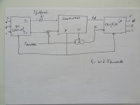
The picture above shows the block diagram for sensorless mode (drive 3). On the left is the conversion from the 3 motor currents to the current vector (in the complex domain, I_r +j*I_i , r stands for real, i stands for imaginary, j is the sqrt(-1)) . In standard literature this is both the Clarke and Park transform in one (when this code was written I didn't know about Clarke and Park..) . This then goes into the loop filters. The output of the loop filters is motor speed (omega in the picture, phi_int in the code), motor phase (phi_motor in the code) and output amplitude (ampli_real in the code). The for FOC necessary voltage shift is directly calculated based on omega*L*I_throttle and placed in ampli_imag in the code. Then on the right the output block calculates the three motor voltages.

There is no observer or anything like that (I actually dont know what that is). Underneath the loopfilter block and output block are further explained.
DSC02270-800x800.jpg

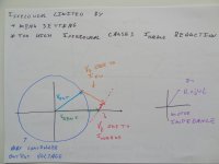
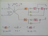
The loopfilters is where things get interesting. The loopfilter part for phase and speed is based on a PLL and contains 2 integrators. The loopfilter part for amplitude (the real part V_r of the amplitude) is a simple first order loopfilter containing only 1 integrator.

The inputs of this block is based on the errors in the motor currents. The loopfilters however directly control the controller output voltages. To make the translation from currents to voltages, a multiplication with the (phase of the) motor impedance is included before the actual loop filters. Ideally the phase of the motor impedance is used here, but if unknown then 45 degrees is also good. The impact of adding this rotator is very interesting. It links both phase and amplitude together. At low speed (where the rotator rotates over 0 degrees as motor impedance is dominated by R) an error in phase results in action taken by the phase control loop, and an error in amplitude is dealt with by the amplitude control loop. But at high speed where the motor L impedance is much higher than motor R, so the rotator rotates over 90 degrees. This means that errors in phase are dealt with by the AMPLITUDE control loop, and error in current amplitude is dealt with by the PHASE control loop. A 'golden', always good phase to rotate over is 45 degrees.

Lastly, before the loopfilters simple quantisers are added. These generate a simple +1 or -1 output based on the sign of their input signals. The effect of these is that the control loops are like Sigma Delta converter control loops, not the more standard PID etc. The quantizers are in series with the unknown motor integrator. Because of the adaptive gain inherent in quantizers (see Sigma Delta theory) this makes the control loops independent of the motor R and L (and this is the reason why Arlo1's Nissan Leaf motor runs with the same control loop coefficients as my 4025 low inductance small RC motor). In laymans terms, the motor L and R determines the amplitude of the signals going into the quantizers. But since the quantizers only output +1 or -1, the size of the signals going into the quantizers does not matter. And therefore motor L and R does not matter. In technical terms, in 1 bit Sigma Delta theory it is known that the single integrator in the control loop representing the 1st order does not matter, its properties ONLY determine the amount of quantisation noise in the loop but it does not impact loop stability. Here the motor L and R are the single integrator representing the 1st order, so therefore the motor properties determine the amount of quantisation noise BUT NOT THE LOOP STABILITY.
DSC02271-800x800.jpg

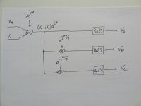
Lastly the output voltages for the 3 output phases are calculated. I do not use SVM or anything like that, each phase is calculated independently of the other 2. Simple 1st order noise shapers are used to deal with the quantisation inherent in the PWM process. The output amplitude of the loop filter (V_r) together with the inductor based (no fieldweakening) voltage shift (V_i) is rotated over motor phase phi . Then controller output phase A is the real part of this complex voltage. For phase B the complex voltage is rotated 120 degrees forward and the real part is taken. For phase C a rotation over -120 degrees is applied.
 
What you have to realise is that running a motor is a 2-dimensional control problem. In a simple sensored FOC motor phase is known and the 2-dimensional control determines the real and imaginary output voltage, based on real and imaginary wanted motor current. For sensorless FOC the imaginary output voltage is known (calculated from motor inductance, throttle current and rotor speed), the 2 dimensional control determine the rotor phase and real output voltage (again based on wanted motor current)

The control is thus always based on wanting 2 variables, namely the motor real current (throttle current) and motor imaginary current (fieldweak current) . To be able to influence these 2 independent variables you NEED to be able to independently control 2 motor controller output variables. For sensorless these 2 independent motor controller output variables are the real amplitude and rotor phase. You CANNOT let the real amplitude run into the limiter ! At that point you only have one control variable left (the phase) and you CANNOT independently influence the 2 input wanted current anymore. You absolutely NEED TWO independent output control variables to be able to control TWO wanted input variables !

To prevent saturation of the output voltage (and thus losing one independent output variable) a scheme was put in place where an increase in output amplitude automatically reduces the throttle current. In such a way the controller will never saturate and you will always have TWO independent control variables available.

DSC02272-800x800.jpg

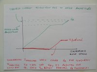
Just before the output voltage limiter starts reducing the throttle current the field weakening kicks in. I think the default for the output voltage limiter to kick in is 98% of max amplitude, while the default for the field weakening is 95%. So once the amplitude exceeds the 95% level the controller automatically starts to ask for (more) field weakening current. The effect of asking for more field weakening current is that the output voltage is automatically reduced (as due to the field weakening the wanted torque current can be achieved for a lower output voltage). The net effect of this is that the output voltage is stuck at 95% while the field weakening current is increased.

Once certain conditions apply and no more field weakening can be applied, the controller output voltage will increase above 95%. Then once it exceeds 98% the wanted torque current will automatically be reduced until a stable operating point is achieved. During this whole process there will always be 2 output variables available to control 2 input variables.

Now the amount of field weakening current you can apply is not an arbitrary thing. On the one hand there is the maximum you want to set based on max phase current, max battery current etc. This is the value entered in the menu structure, where I recommend 0A if you want no field weakening (it will just pass the 95% level without applying field weakening) or 70% of max phase amps if you do want field weakening. The thing is though that if you apply TOO MUCH field weakening the motor will actually SLOW DOWN !! There is a second condition determining the max field weakening current that you can apply !

DSC02273-800x800.jpg

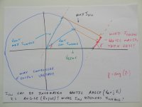
In the above picture the blue circle represents all possible max output voltages the controller can generate. In the above picture in this particular case the controller output voltage is the light blue voltage vector V_out. The motor voltage is the green vector (along the real axis) V_bemf. Notice that this voltage is larger than the controller can generate. On top of the green motor voltage vector you have the pink motor impedance voltage vector as caused by the real motor current I_torque. This vector is somewhere along a line (dotted pink) at an angle determine by the motor impedance (in purple). Finally the orange voltage vector is the motor impedance combined with the imaginary motor current I_fieldweak. This orange vector is always at a 90 degrees angle with the pink vector. Note that the sum of motor V_bemf (green vector) and motor impedance voltage (pink and orange vectors) ALWAYS adds up to the controller output voltage vector (light blue) and that this is ALWAYS on the dark blue circle of max possible output voltages.

DSC02274-800x800.jpg

Increasing the field weakening curent I_fieldweak means an increase in lenght of the orange voltage vector. This causes a move of the light blue controller output voltage vector along the dark blue circle of max possible voltages. In this way the pink voltage vector is stretched out, meaning a higher I_torque is achieved. This then in turn means more motor torque and probably a higher motor speed.

But you can see from the picture that there is a maximum. There is a clear tipping point where the sum of light blue vector and orange vector leads to a maximum length of the pink vector.

DSC02275-800x800.jpg

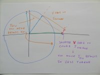
Increasing the orange vector will lead to a decrease of pink vector. Meaning more field weakening current will actually lead to a reduction in torque current.

The limit for the length of the orange vector is there where the angle of the light blue vector is that of the pink vector. Or: the limit for the fieldweakening current is there where the angle of the controller output voltage vector is that of the motor impedance.

So the controller increases the field weakening current to try to maintain the 95% output voltage level. All the while it observes the controller output voltage angle and compares this to the motor impedance angle. If the voltage angle exceeds the impedance angle it will stop increasing the field weakening current. This is a dynamic process as there are constant changes in motor speed (changes the impedance angle !) and motor controller output voltage vector (remember that this is controlled by the 2 control loops on which the field weakening has no impact).

This is the reason that the actually applied field weakening current is typically less than the set maximum, is constantly changing and in practise is difficult to predict.
 
Two improvement suggestions based on comments received:

- For the rotation in the loopfilters (from current to voltage, as explained above) it always uses the motor impedance angle. When this angle is wrong the controller can go unstable under high load. For this reason Arber333 and Arlo1 had to experiment with motor inductance / resistance for the controller to be stable. My experience is that not using the motor impedance angle but using a fixed 45 degree angle is ALWAYS stable. The drill with the Sensorless From Standstill was using 45 degree for the rotation, and not the motor impedance. I would add a menu option where one can chose between impedance angle and fixed 45 degree angle.

- In the fieldweakening post I discuss how the amplitude of the controller output voltage kickstarts fieldweakening and ultimately torque current limiting. In the current implementation a shortcut is taken where it only looks at the real part of the motor output voltage for this. Better is to use the actual voltage vector lenght, so using both real and imaginary parts.... This is my best guess why Arlo1's car used to sometimes conk out at high speed under field weakening.
 
This should be on a GitHub repository and all the technical explanation (in wiki/text with picture) and pictures should be stored in the same repository, this way, users could download the zip file if the repository and get an archive of all the project: sources code and the documentation files.

Thank you for sharing.
 
Lebowski said:
but the large amount of work plus not being able to use the end result myself prevents me from doing so.
I feel the same, the best motivation (when no one is paying you to do such) is to use the thing and take value out of it, preferably if we can use it/take out value from it daily. If we don't use it, why would we do it? And how would we test it without using it? How would we understand the development path/most important features?

Other thing I was seeing is that it is not possible to see the source code without using that specific IDE. Again, I should be a text file ASM so everyone can see on web/mobile/PC, that way it will also work with revision control like got.
 
? The zip file contains a directory ending in .X . If you go in this directory you can look at the code in the .s files with a simple text editor. I just zipped my entire directory though so half the .s files are old and no longer used... the IDE will only show the ones actually uses so it does make it a bit clearer.

I dont know about windows, I use linux and there opening a .s with a text editor is no problem...

I agree by the way with your points... its a pity... the code here works fine but needs a major cleanup. Then combined with the Sensorless from Standstill would yield a beautiful controller... but why spend the 100s of man hours if I cannot use the result ?
 
Lebowski said:
I dont know about windows, I use linux and there opening a .s with a text editor is no problem...

I agree by the way with your points... its a pity... the code here works fine but needs a major cleanup. Then combined with the Sensorless from Standstill would yield a beautiful controller... but why spend the 100s of man hours if I cannot use the result ?
I use Linux also. If you will not do it, I plan to share your code and your notes in a github repository. It will help for sure others like me to learn motor control.
 
Thanks for Sharing Bas. This will be a huge step forward for many.
 
Absolutely thank you for sharing Bas! Kindest disclosure I have seen this year. Will sure assist the community! :bigthumb:
 
Thank you for SC Bas. We will try to develop ESC WiFi interface for it asap...

A
 
I did an archive of the shared sources and notes on a Github so it is very easy to see the sources code on any device as also to save the full sources + technical notes!! This is very important for me because I will be reading this notes in recent future using my mobile phone - I would like to implement field weakening on our TSDZ2 OpenSource firmware in a way to increase the motor power and pedal cadence over the max value of 90 RPM.

Here the archive: https://github.com/casainho/Lebowski-controller-IC

image.png
 
Thank you for the explanation of how your code works and the source code. I feel like I am riding on a magic carpet driving my scooter with a Lebowski controller as it is so quiet and the torque control is brilliant. :bigthumb:
 
casainho said:
I did an archive of the shared sources and notes on a Github so it is very easy to see the sources code on any device. This is very important for me because I will be reading this notes in recent future using my mobile phone - I would like to implement field weakening on our TSDZ2 OpenSource firmware in a way to increase the motor power and pedal cadence over the max value of 90 RPM.

Can you move it to a more general location ? The controller is not e-bike specific but alos for cars, motorcycles, scooters etcetc, it should be in a general motor controller section. Also can you mention that I am the origin (B.M. Putter) and my email address (bmp72 @ hotmail.com) .
 
Lebowski said:
casainho said:
I did an archive of the shared sources and notes on a Github so it is very easy to see the sources code on any device. This is very important for me because I will be reading this notes in recent future using my mobile phone - I would like to implement field weakening on our TSDZ2 OpenSource firmware in a way to increase the motor power and pedal cadence over the max value of 90 RPM.

Can you move it to a more general location ? The controller is not e-bike specific but alos for cars, motorcycles, scooters etcetc, it should be in a general motor controller section. Also can you mention that I am the origin (B.M. Putter) and my email address (bmp72 @ hotmail.com) .
The other option are to put in my own private space, I will do it. Other option would be to do it yourself, now would be really quick for you by just copy paste what I did.

Ok, I will mention your name and your e-mail. As you can see, I did kept your original message (including a screenshot) and put a link to this thread.

Should I add other links? Like links to other threads about your project or such?
 
Done: https://github.com/casainho/Lebowski-controller-IC
 
Very interesting, thanks for sharing.
On the loopfilter block diagram the two outputs of the multiplier (rotator) are the imaginary and the real parts? Imaginary is used to obtain omega/phi and real for Vr?
 
peters said:
Very interesting, thanks for sharing.
On the loopfilter block diagram the two outputs of the multiplier (rotator) are the imaginary and the real parts? Imaginary is used to obtain omega/phi and real for Vr?

Yes... so when you have a positive imaginary part after the rotator it will increase both the speed and phase variables in the loop filter .
 
Thank you Bas, I realise how frustrating it is to not get exactly what you initially envision from a project. I think this step along with putting that source onto github is a huge step forward and will help so so many more people use your work for the greater good, both from a learning perspective and through more people being able to build there own designs.

Kiwifiat (roger) is helping me revive my old controller which i messed up with the wrong resistor types.

My hope here is that with the source now open we will catch up with the vesc style controllers.

I imagine BobC is smiling down on us all probably wearing his electrical HV safety sandals saying "what could possibly go wrong?"

Anyway I hope you are well and i'm sorry i haven't yet got round to meeting you in person.

regards Andy
 
Lebowski said:
For regen however the receiving voltage is the stator voltage, so for regen the 90 degree shifted voltage is not added and the controller operates as a Stator Oriented Controller. This gives less than maximum (braking) torque, but does give maximum current back into the battery (max regen efficiency).

What kind of change is necessary to create maximum braking torque instead, for use cases where that is more important than energy recovery?


(not that I know how to code at all, much less something like this, but it might help someone else do it ;) ).
 
I tried running the Outlander motor with new firmware 2B0. I can see it is more stable just by running it without load.
But when starting from still motor wiggles anyways. I thought it would just turn into one direction.

I will try and connect inverter to Leaf EM61 motor in my car now. I will test it under load.
I will report back when i have results.
 
Lebowski i got an idea... and that could be good, or it could be disaster. You never know by me :).

How is the throttle function used in code? Is it possible to use it as auto-throttle with a timer and a single input?
Instead of analog input there would be 1 or 0 (5V signal) If signal would be 1, function would ramp up over some time and after this time elapsed it would run at like 75% throttle. Maybe acceleration limiter could be used for this?
Also function at 0 would drop throttle and wait for new signal.
Could that kind of use be set into your throttle menu? That way we wouldnt need multiple code?

I could just try with V signal on throttle1 and resistor divider so i would get like 3V3 signal. Then setup acceleration limiter really lame so compressor would spool up slowly and remain at some RPM. Worth a try!
 
arber333 said:
Lebowski i got an idea... and that could be good, or it could be disaster. You never know by me :).

How is the throttle function used in code? Is it possible to use it as auto-throttle with a timer and a single input?
Instead of analog input there would be 1 or 0 (5V signal) If signal would be 1, function would ramp up over some time and after this time elapsed it would run at like 75% throttle. Maybe acceleration limiter could be used for this?
Also function at 0 would drop throttle and wait for new signal.
Could that kind of use be set into your throttle menu? That way we wouldnt need multiple code?

I could just try with V signal on throttle1 and resistor divider so i would get like 3V3 signal. Then setup acceleration limiter really lame so compressor would spool up slowly and remain at some RPM. Worth a try!

You can also have the resistor divider to make 3V3, and add a big capacitor so that the throttle value ramps up slowly. You have to make sure that after reset the capacitor is discharged (which would be the case when there is no supply, or you can use the drive 0 or 1 signal for this)
 
Back
Top