TDSZ2 : HOWTO - Motor Hall Sensors replacement (originally Error 3 "Torque Fault" ?)

pagaille

10 mW
Joined
Apr 16, 2020
Messages
27
UPDATE : I fixed it !

See below my howto (https://endless-sphere.com/forums/viewtopic.php?f=30&t=107538&p=1574314#p1575968) to fix the motor inner hall sensor.


Hi,

I need help to understand what's wrong with my motor who died during a maintenance. 🙁 It's a TSDZ2 running the Opensource-Ebike-Firmware 1.0.

What's wrong ?
Motor doesn't work anymore : it emits a small buzz but doesn't turn. It makes a somewhat louder 'tick' when cutting power. When pedalling or activating the Walk mode, the display soon shows "3 : Torque Fault"
(NB : Actually the display is corrupted on the SW102 (line too long) but I was able to guess the error message by looking at the code)

What did I do ?
I added a temperature sensor, which is working perfectly. I had no particular issue while soldering the wires.
I didn't dismantled the axle containing the torque sensor, only the chainring.
Everything is correctly connected, I double checked. The motors turns freely.

Possible causes
During the operation I removed the motor to check the blue gear state. I had an issue while screwing back the three wires : I overtightened one of the three screws and broke the thread. I installed a bigger screw but it turned out that the new one was a bit too long and was touching the metal case. I thought it could be the reason (one phase missing) but fixing the problem didn't helped.
Maybe the controller is fried ? I'm not sure that the motor case is connected to the ground.
I don't understand how and why the Torque sensor could be wrong. Moreover, the error messages is also displayed as soon as I activate the Walk mode.

What could I do to further diagnose that problem ?

Thanks for your help.

Matthieu
 
Sure, but that’s a somewhat tedious task. Maybe there will be other ideas before I try that ?
 
My motor stopped giving power. Reason was black and red wires coming from torque disk to controller were broken in the root of the disk. Both wires were broken so I think for any reason disk has rotated in place and cutted wires. I soldered wires back. After reassembling motor worked again. This is quite easy to check after opening controller cover and pulling lightly the wires. Or better by unplugging connector and measuring there is no resistance between black and red wires
 
That error name is not correct on the firmware, must be corrected.

Error numbers 3 happens because the motor is pulling current but not rotating, it is blocked. Maybe the hall sensors connector has any issue?? Check the hall sensor signal on the advanced Technical menu.
 
jtsavola said:
My motor stopped giving power. Reason was black and red wires coming from torque disk to controller were broken in the root of the disk.

I measure 2,7 ohms. I guess the sensor is electrically ok. Thanks anyway.
 
casainho said:
Error numbers 3 happens because the motor is pulling current but not rotating, it is blocked. Maybe the hall sensors connector has any issue?? Check the hall sensor signal on the advanced Technical menu.

Spot on. The display shows somewhat random numbers between 5 and 7. Sometimes 4 appears too. Let’s dismantle it to understand what’s wrong.

Thanks !
 
casainho said:
That error name is not correct on the firmware, must be corrected.

This is how it appears : https://nextcloud.gaillet.be/index.php/s/WYjSfq47M2Jy27t
 
So the hall sensor has indeed a problem.

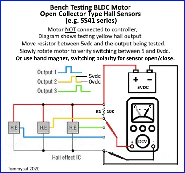
I tested using the method provided on this thread : https://endless-sphere.com/forums/viewtopic.php?f=3&t=105444&p=1543436&hilit=led+hall#p1543566

NktFBwJ.jpg


With the sensor connected to the controller I measure voltages either 0 V or +5V between the black wire and the green or yellow wire, depending on the rotation, but not on the blue wire which stays high. The latter looks ok from the outside.

Any advice ? Should I buy a new motor ? Is it even doable to replace one of those sensors ?
 
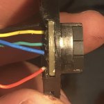
Update. Found the hall sensors that are actually mounted just beside the screw power terminals behind a black silicon paste.

Here are some pictures. I tried to resolder the joints without success.

51910AC4-6E10-4103-A8B1-A543D2DCEA46-8292-000001F05666C4F9.jpg
24553166-9943-42DC-AA83-C6CDB6A0009C-8292-000001F0BC921562.jpg

That PCB is really small and looks glued to the plastic support. Chances are that any tentative to replace the defective hall sensor will break everything.

I'll try to find a replacement PCB or assembly, but I'm not very optimistic. Maybe someone with a fried motor but working sensors assy would sell it to me ?
 
FIXED !

So, being of out luck finding the replacement hall sensor assembly, I tried to fix it. Actually it wasn't so difficult.
It requires some good soldering skills, lot of flux, desoldering braid, a desoldering pump, and a fine tip for your soldering iron.

Here is my repair guide !

The PCB is held in place by the sensors themselves. Once the sensors are unsoldered, the board will be freed.

  • Apply flux all over the sensors pads (three pads per sensor). I don't recommend unsoldering the wires if they are ok since their pad holes are really tight. I have had difficulties to resolder them.
  • Heat and use the desoldering braid to remove most of the solder on the sensor pads
  • Then remove the remnants using the desoldering pump
  • Use a pair of pliers to firmly pull the sensors out, maybe while heating the pads at the same time. That's quite difficult and chances are that you'll break the component. I found easier to cut the terminals (break the component), then pull the PCB out, then use a plier to remove the terminals.
    35D62CA2-F0C1-42B5-8FC2-42D735000073-3957-000000E9981DCF63.jpg
  • The component is the classic Honeywell SS41 https://sensing.honeywell.com/SS41-bipolar. The price is low and I believe that it's good to change all the three sensors by a genuine one instead of the Chinese copy that was probably used.
  • Clean carefully the PCB
  • Solder the replacement sensors. I used my iPhone's magnifier tool to help as the pads are really small.
  • Test. Enjoy your ride
 
Hi, the same error occured on my system. The strange thing is that i parked my velomobile without any error/defect (approx. 800km driven so far).
But when i wanted to go for another drive, a couple of days later, the light did not turn on and i noticed there was no support any more :cry:

I disassembled the motor but was not able to check the hall sensors properly, seems like none of them shows any value...? I used a power supply to check and not the battery, would that be the reason?

Walk assist does not provide any 'support', btw, so it seems like the motor is not rotating.

Maybe i am doing something wrong, can someone elaborate on the relation of the light and this issue?

Target is to disassemble the battery as well and test the system as a set away from the velomobile (hard to work on the system when it is mounted).
I would appreciate any tip!
 
This post inspired me to try replacing my hall sensors. Adding some additional photos and information for the future.

My motor suddenly stopped working at the beginning of my commute back home one night. I was going a few miles per hour, almost at a standstill, behind a shuttle bus waiting to exit the parking lot. When I began to pedal the motor started making noise and I could barely feel any assist. I pulled over and tested the throttle / walk assist and the motor would only click and hum for a brief second, or sometimes made a grinding noise for a few seconds. There was no error code on my VLCD5 display.

At first I thought maybe the blue gear was stripped, but it turned out to be fine. I unmounted the motor and found that even with no load it would not spin, only vibrate in my hand for a moment. I replaced the controller board with a spare I had on hand but that did not change anything. Finally I remembered to test the hall sensors with a multimeter and found that the number 2 sensor (green wire) was stuck at 0V. This video shows both the exact same symptoms I had and how to test the voltages:
https://www.youtube.com/watch?v=ceu565xA1Dk

I uploaded some photos to imgur and added some captions describing the process of removing the sensors. I hope someone finds this useful.
https://imgur.com/a/4nqUjno

Unfortunately my desoldering skills suck so I had no luck removing the old sensor leads from the PCB. I ended up scrapping the PCB entirely and simply manually wired together the leads of the new sensors together and sealed up the abomination in hot glue. Surprisingly everything works so far, but only time will tell how long this will last. :lol:

It would be really great if we could procure just the black plastic assembly with hall sensors as a replacement part (see: https://imgur.com/fmHGsLD) as that would make this a 5 minute repair. Instead we have to do this kind of delicate surgery or replace the whole inner motor for $100+.
 
Back
Top