Custom board Lishui FOC

Slipy

10 mW
Joined
Mar 19, 2020
Messages
25
IMG-dae05b96909fa8441195acf5168c7ffd-V.jpg[youtube]https://www.youtube.com/watch?v=62B7nJV4lMw&feature=youtu.be[/youtube]Hello everyone, I saw the firmware Lishui foc by @stancecoke, and decided to make my own board, the board was based only on my knowledge and firmware, as well as on a photo of the operational amplifier. And well, it works. This is the first version of the board, it has brakes, an auto-calibration button, a reverse button, a brake light, a main light, a pas sensor and a throttle stick, eeprom is implemented in the EBICS firmware, and this gives a lot of possibilities, displays can be completed, sensorless calibration (motor inductance and resistance) and many different functions. If you wish, I can publish gerber files, or I can draw the following versions of the board. It should be noted that the board consists of modules (three drivers and dc-dc step-down)IMG-f8bbadafbd82afbd6a17d100ee3304e7-V.jpg
 
Yes please open source everything.

Even better, get a batch of boards made, set up a detailed BoM for automated ordering, detailed howto for noobs

so anyone can get hands-on for testing and feedback!

Will you be iterating further versions?
 
Slipy said:
I saw the firmware Lishui foc
Thank you, Slipy, for the hardware development! :thumb:

The firmware was mainly developed for adding bottom bracket torquesensor support to the Lishui FOC controllers, that are used in several "Discounter" E-Bikes from European manufacturers like Prophete, Fischer, NCM ...

But of course it works with a simple thumb throttle, too.

There's a grapic user interface for setting parameters and flashing. Bafang-, Kunteng- and Kingmeter Displays are supported. A mobile app is in development, main functions are working already :wink:

The repo can be found at github:
https://github.com/EBiCS/

regards
stancecoke

73279090


68747470733a2f2f7777772e706564656c6563666f72756d2e64652f77696b692f6c69622f6578652f66657463682e7068703f63616368653d26773d39303026683d34363226746f6b3d363536646630266d656469613d656c656b74726f746563686e696b3a73637265656e73686f746775692e706e67


index.php
 
john61ct said:
Yes please open source everything.

Even better, get a batch of boards made, set up a detailed BoM for automated ordering, detailed howto for noobs

so anyone can get hands-on for testing and feedback!

Will you be iterating further versions?
Yes, the next versions will definitely be. But this is a beta version, for testing the firmware.
We have to try and help @stancecoke write the firmware (for example, measuring the resistance and inductance of the motor) on github I will post my version of the firmware for this board (will be updated)
https://drive.google.com/file/d/10szukm4fZVd5b291nL5WrsW4DPxwZVVs/view?usp=sharing (BOM's and GERBER's)
https://github.com/arozhkov2001/EBiCS_Firmware (Firmware adapted to Custom Board)
 
Slipy said:
for example, measuring the resistance and inductance of the motor
these things are "nice to have" but not really necessary. A sensorless branch based on the observer used in the VESC project already exists, resistance and inductance are set in the config.h at the moment.

regards
stancecoke
 
Hello People! Thank you for your amazing work.
I have few Lishui FOC controllers, that looks like that:
2021-04-01 00.41.49.jpg

On the paper I have done reverse engineering of schematic (had to desolder wires)
Also one of them I got rid of aluminium case, and have maid my "experimentation" board:
2021-04-01 00.42.24.jpg

I need a little bit of help and advise.
My problem is that in your firmware port PB8 is PAS sensor. But in my version it is +V Battery main voltage sensor (ADC).
I have just started with STM32 and for me is "brain explode" how to reconfigure ADC init.
Could you please help to reconfigure PB8 as Voltage Sense (+V) ?
Also in my version i have Temperature sensor on PB1. This is interesting controller. It has also some kind of CURRENT comparator(may be, overcurrent protection, not sure. Maybe it is ADC input too) on PB12 sensing 220ohm on every phase shunt. Also I have 3 Phase Current Measure resistors exactly like in yours controllers (With all PWM, Halls etc)
in perfect i would like to have:

PA3 - ADC Throttle (as it is now)
PB8 - ADC Main Voltage+
PB1 - ADC Temperature (as it is now)
PA7 - ADC - in my model it is DC-DC V+ sensor.( Dont need it, But maybe in future will desolder and put some my sensor here)


Thats pretty it with ADCs
GPIOS I can remap myself on any other ports, it is quite easy.

THANK THANK!
Thank you a lot!

Code:
/* ADC1 init function */
static void MX_ADC1_Init(void)
{

  ADC_MultiModeTypeDef multimode;
  ADC_InjectionConfTypeDef sConfigInjected;
  ADC_ChannelConfTypeDef sConfig;

    /**Common config 
    */
  hadc1.Instance = ADC1;
  hadc1.Init.ScanConvMode = ADC_SCAN_ENABLE; //Scan muß für getriggerte Wandlung gesetzt sein
  hadc1.Init.ContinuousConvMode = DISABLE;
  hadc1.Init.DiscontinuousConvMode = DISABLE;
  hadc1.Init.ExternalTrigConv = ADC_EXTERNALTRIGCONV_T3_TRGO;// Trigger regular ADC with timer 3 ADC_EXTERNALTRIGCONV_T1_CC1;// // ADC_SOFTWARE_START; //
  hadc1.Init.DataAlign = ADC_DATAALIGN_RIGHT;
  hadc1.Init.NbrOfConversion = 7;
  hadc1.Init.NbrOfDiscConversion = 0;


  if (HAL_ADC_Init(&hadc1) != HAL_OK)
  {
    _Error_Handler(__FILE__, __LINE__);
  }

    /**Configure the ADC multi-mode 
    */
  multimode.Mode = ADC_DUALMODE_REGSIMULT_INJECSIMULT;
  if (HAL_ADCEx_MultiModeConfigChannel(&hadc1, &multimode) != HAL_OK)
  {
    _Error_Handler(__FILE__, __LINE__);
  }

    /**Configure Injected Channel 
    */
  sConfigInjected.InjectedChannel = ADC_CHANNEL_4;
  sConfigInjected.InjectedRank = ADC_INJECTED_RANK_1;
  sConfigInjected.InjectedNbrOfConversion = 1;
  sConfigInjected.InjectedSamplingTime = ADC_SAMPLETIME_1CYCLE_5;
  sConfigInjected.ExternalTrigInjecConv = ADC_EXTERNALTRIGINJECCONV_T1_CC4; // Hier bin ich nicht sicher ob Trigger out oder direkt CC4
  sConfigInjected.AutoInjectedConv = DISABLE; //muß aus sein
  sConfigInjected.InjectedDiscontinuousConvMode = DISABLE;
  sConfigInjected.InjectedOffset = ui16_ph1_offset;//1900;
  HAL_ADC_Stop(&hadc1); //ADC muß gestoppt sein, damit Triggerquelle gesetzt werden kann.
  if (HAL_ADCEx_InjectedConfigChannel(&hadc1, &sConfigInjected) != HAL_OK)
  {
    _Error_Handler(__FILE__, __LINE__);
  }

  /**Configure Regular Channel
  */
sConfig.Channel = ADC_CHANNEL_7; //battery voltage
sConfig.Rank = ADC_REGULAR_RANK_1;
sConfig.SamplingTime = ADC_SAMPLETIME_1CYCLE_5;//ADC_SAMPLETIME_239CYCLES_5;
if (HAL_ADC_ConfigChannel(&hadc1, &sConfig) != HAL_OK)
{
  _Error_Handler(__FILE__, __LINE__);
}


/**Configure Regular Channel
*/
sConfig.Channel = ADC_CHANNEL_3; //Connector SP: throttle input
sConfig.Rank = ADC_REGULAR_RANK_2;
sConfig.SamplingTime = ADC_SAMPLETIME_1CYCLE_5;//ADC_SAMPLETIME_239CYCLES_5;
if (HAL_ADC_ConfigChannel(&hadc1, &sConfig) != HAL_OK)
{
_Error_Handler(__FILE__, __LINE__);
}
/**Configure Regular Channel
*/
sConfig.Channel = ADC_CHANNEL_4; //Phase current 1
sConfig.Rank = ADC_REGULAR_RANK_3;
sConfig.SamplingTime = ADC_SAMPLETIME_1CYCLE_5;//ADC_SAMPLETIME_239CYCLES_5;
if (HAL_ADC_ConfigChannel(&hadc1, &sConfig) != HAL_OK)
{
_Error_Handler(__FILE__, __LINE__);
}
/**Configure Regular Channel
*/
sConfig.Channel = ADC_CHANNEL_5; //Phase current 2
sConfig.Rank = ADC_REGULAR_RANK_4;
sConfig.SamplingTime = ADC_SAMPLETIME_1CYCLE_5;//ADC_SAMPLETIME_239CYCLES_5;
if (HAL_ADC_ConfigChannel(&hadc1, &sConfig) != HAL_OK)
{
_Error_Handler(__FILE__, __LINE__);
}
/**Configure Regular Channel
*/
sConfig.Channel = ADC_CHANNEL_6; //Phase current 3
sConfig.Rank = ADC_REGULAR_RANK_5;
sConfig.SamplingTime = ADC_SAMPLETIME_1CYCLE_5;//ADC_SAMPLETIME_239CYCLES_5;
if (HAL_ADC_ConfigChannel(&hadc1, &sConfig) != HAL_OK)
{
_Error_Handler(__FILE__, __LINE__);
}

/**Configure Regular Channel
*/
sConfig.Channel = ADC_CHANNEL_8;
sConfig.Rank = ADC_REGULAR_RANK_6; // connector AD2
sConfig.SamplingTime = ADC_SAMPLETIME_1CYCLE_5;//ADC_SAMPLETIME_239CYCLES_5;
if (HAL_ADC_ConfigChannel(&hadc1, &sConfig) != HAL_OK)
{
_Error_Handler(__FILE__, __LINE__);
}

/**Configure Regular Channel
*/
sConfig.Channel = ADC_CHANNEL_9; // connector AD1, temperature or torque input for Controller from PhoebeLiu @ aliexpress
sConfig.Rank = ADC_REGULAR_RANK_7;
sConfig.SamplingTime = ADC_SAMPLETIME_1CYCLE_5;//ADC_SAMPLETIME_239CYCLES_5;
if (HAL_ADC_ConfigChannel(&hadc1, &sConfig) != HAL_OK)
{
_Error_Handler(__FILE__, __LINE__);
}

}

/* ADC2 init function */
static void MX_ADC2_Init(void)
{

  ADC_InjectionConfTypeDef sConfigInjected;

    /**Common config 
    */
  hadc2.Instance = ADC2;
  hadc2.Init.ScanConvMode = ADC_SCAN_ENABLE; //hier auch Scan enable?!
  hadc2.Init.ContinuousConvMode = DISABLE;
  hadc2.Init.DiscontinuousConvMode = DISABLE;
  hadc2.Init.ExternalTrigConv = ADC_SOFTWARE_START;
  hadc2.Init.DataAlign = ADC_DATAALIGN_RIGHT;
  hadc2.Init.NbrOfConversion = 1;
  if (HAL_ADC_Init(&hadc2) != HAL_OK)
  {
    _Error_Handler(__FILE__, __LINE__);
  }

    /**Configure Injected Channel 
    */
  sConfigInjected.InjectedChannel = ADC_CHANNEL_5;
  sConfigInjected.InjectedRank = ADC_INJECTED_RANK_1;
  sConfigInjected.InjectedNbrOfConversion = 1;
  sConfigInjected.InjectedSamplingTime = ADC_SAMPLETIME_1CYCLE_5;
  sConfigInjected.ExternalTrigInjecConv = ADC_INJECTED_SOFTWARE_START;
  sConfigInjected.AutoInjectedConv = DISABLE;
  sConfigInjected.InjectedDiscontinuousConvMode = DISABLE;
  sConfigInjected.InjectedOffset = ui16_ph2_offset;//	1860;
  if (HAL_ADCEx_InjectedConfigChannel(&hadc2, &sConfigInjected) != HAL_OK)
  {
    _Error_Handler(__FILE__, __LINE__);
  }

}

P.S. I already tried before to put your compiled firmware via ST-link. All is good, my test Motor spins. I have bypassed PAS in main While loop for test. but having no main voltage.
 
First: great work :)

Fluctuator said:
I have few Lishui FOC controllers, that looks like that:
Where are they from? Ebikes? Scooters?

Fluctuator said:
Could you please help to reconfigure PB8 as Voltage Sense (+V) ?

Sorry, but PB8 is no ADC input, you can't read in the voltage with this pin. See the datasheet.
For discussion of the firmware, please join the german forum, in this forum the project has met with little interest so far.
https://www.pedelecforum.de/forum/index.php?threads/open-source-firmware-f%C3%BCr-lishui-controller.61113/

stancecoke said:
It has also some kind of CURRENT comparator
That's standard at the Lishui design. Normally it's the fourth channel of the quad op amp (3x phase current, 1x comparator) for Tim1 BKIN on PIN PB12. That's a safety feature for switching off the PWM at overcurrent.

regards
stancecoke


fetch.php


PB8 function.PNG
 
stancecoke said:
First: great work :)
Nice to hear from you, stancecoke.

Fluctuator said:
I have few Lishui FOC controllers, that looks like that:

Where are they from? Ebikes? Scooters?


This controllers I found in a box of electronics scrap near trash bin on one of the streets in Berlin about one year ago. There were also some printer parts, broken mobile phones, few lipo-batteries, BMS, etc.
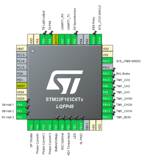
I dont think this FOC controllers from E-Bikes. More chances it is from Scooters. On PA3 port is wire with "TB" mark. I gUess it is maybe light.
Also on PB5 it has digital out with diode, involved in power circuit manage. So I need also to reconfigure it. as well, But cant understand yet how to reconfigure interrupt as well :))) I would like to put it on PB8, because I replaced PAS from PB8 to PB4 (on this controller this pin is not connected anywhere, free)

Fluctuator said:
Could you please help to reconfigure PB8 as Voltage Sense (+V) ?

Sorry, but PB8 is no ADC input, you can't read in the voltage with this pin. See the datasheet.
For discussion of the firmware, please join the german forum, in this forum the project has met with little interest so far.
https://www.pedelecforum.de/forum/index.php?threads/open-source-firmware-f%C3%BCr-lishui-controller.61113/

THANKS A LOT! I just saw there voltage divider (Strangely, it makes from 42V -> 4.5V, and how it didn't burn digital input)
I just decided to cut the PCB trace, and now nothing comes to PB8. As I said I want to put there Speed sensor, cause it is easy to access pin on PCB.

On PA7 in this controller comes voltage divider which makes 1.3V from 20V. This 20V coming out of DC-DC step down. It also is feeding MOSFET drivers IR2103. Why does Lishui designer sense DC-DC I have no Idea. I think it will always gonna stay 20V even if battery voltage goes down. I will check later. I can also cut PCB trace and solder a wire from +Vbattery divider to PA7. Its quite easy. But afraid of 4.5V input to ADC. Need to check in datasheet if it is tolerant

stancecoke said:
It has also some kind of CURRENT comparator
That's standard at the Lishui design. Normally it's the fourth channel of the quad op amp (3x phase current, 1x comparator) for Tim1 BKIN on PIN PB12. That's a safety feature for switching off the PWM at overcurrent.

regards
stancecoke


Its big progress for me today! I will go to check your German forum link now. Thank you, again.

Spinning:)))))))) :
2021-04-01 22.30.43.jpg

BTW, microcontroller on this Lishui: Stm32f103c8

I would like also to find out what is normal operating temperature of FOC controllers, to make proper size aluminium heat sink. I tried this Lishui today on 42V 0.8A for maybe 10 minutes, temperature of aluminium pad is about 40 celcius. I have few cheap no name BLDC controllers in my diy electric bicycles, and they are not hot after even 1 hour.
 
Impressive work here with the hardware reverse engineering!

Fluctuator said:
Also in my version i have Temperature sensor on PB1. This is interesting controller. It has also some kind of CURRENT comparator(may be, overcurrent protection, not sure. Maybe it is ADC input too)

My motor has a termistor in order to monitor the temperature. The cable of the thermistor connects to the PB5 pin (SS connector on the lishui print). Could that be an explanation for some kind of current measurement circuit on the board -> measuring the current through
the thermistor at constant voltage (from PB5) would be an indicator of the temperature.

I'm just guessing, i'm not an electronics hardware expert :)
 
benno said:
Impressive work here with the hardware reverse engineering!

Fluctuator said:
Also in my version i have Temperature sensor on PB1. This is interesting controller. It has also some kind of CURRENT comparator(may be, overcurrent protection, not sure. Maybe it is ADC input too)

My motor has a termistor in order to monitor the temperature. The cable of the thermistor connects to the PB5 pin (SS connector on the lishui print). Could that be an explanation for some kind of current measurement circuit on the board -> measuring the current through
the thermistor at constant voltage (from PB5) would be an indicator of the temperature.

I'm just guessing, i'm not an electronics hardware expert :)

Temperature from Thermistor is measured by voltage level. So yours PB5 is ADC input I guess.
 
Back
Top